Check worst-case receive sensitivity and receiver overload using explicit optic and plant limits.
Networking
Fiber loss and receive-power worksheet
Check worst-case receive sensitivity and receiver overload using explicit optic and plant limits.
Example inputs · Replace these with your measurements to build your plan.
Method, example and sources
Enter minimum and maximum transmit power and receiver limits in dBm.
Build minimum and maximum plant loss from fiber, connector, splice and other terms.
Check low receive power against sensitivity plus the chosen margin.
Check high receive power independently against the receiver's maximum input.
Worked example. A link can have plenty of sensitivity margin while too little attenuation lets the transmitter overload its receiver. Both ends of the permitted receive window matter.
Check low receive power and overload independently
Both transmit extremes and plant-loss extremes are used; dBm power is not added like watts.
Minimum plant loss
1.1dB
Maximum plant loss
3.2dB
Worst low receive power
-8.2dBm
Worst high receive power
-3.1dBm
Sensitivity margin
5.8dB
Overload headroom
0.1dB
Loss budget after reserve
6dB
Fiber loss and receive-power worksheet: detailed result
Check
Entered outcome
Sensitivity plus reserve
Within entered limit
Receiver overload
Within entered limit
Use the correct wavelength, optic pair and temperature/configuration limits.
Within a power budget does not establish reach, dispersion, polarity, coding or host compatibility; measure the installed plant.
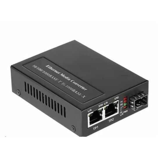
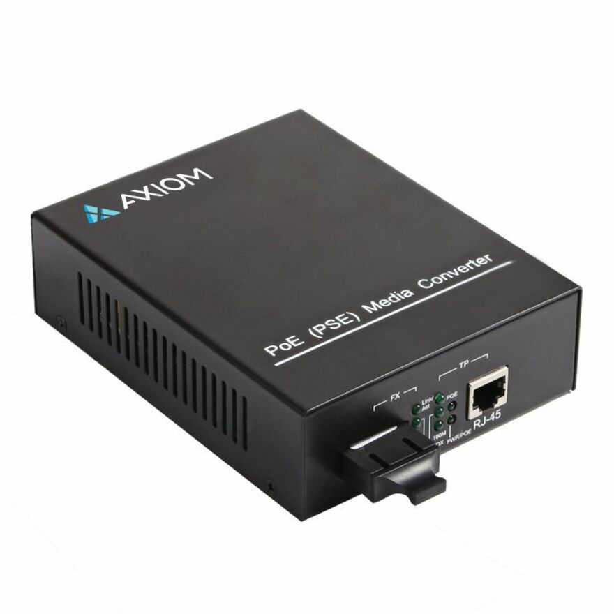
From the catalog
Transceivers/Media Converters
Explore related listings, then confirm the exact model requirements against your plan. These listings are not an automatic compatibility or capacity verdict.
An optical receiver has a low-power sensitivity and a maximum input limit. The lowest transmit output with the highest plant loss tests one boundary; the highest output with the lowest loss tests the other. Use the correct wavelength, temperature and configuration limits from the exact optic documents. A typical figure cannot replace a documented extreme in a worst-case check.
Budget does not establish interoperability
Plant loss is entered here as an engineering scenario and should be measured after installation. Passing these arithmetic comparisons does not prove supported reach, dispersion, fiber type, polarity, paired wavelength or host coding. Keep the exact optic pair and both receiver limits available. Connector and splice counts also need an explicit definition so a mated pair is not accidentally counted twice.
Worked example
A link can have plenty of sensitivity margin while too little attenuation lets the transmitter overload its receiver. Both ends of the permitted receive window matter.