ANSI/TIA-568/569/606/607 · ANSI/BICSI N1-2019 · NEC Art. 725/770/800
Deliverables
Certified link test results · TIA-606 labeling · as-built records
Delivery
Scoped per site survey · routed to quote/RFQ · NDAA §889 screened
Overview
The physical layer, engineered to standard before anything rides on it
Cable plant is the one part of a building's technology that is expensive to get wrong twice, because the second attempt means opening the walls again. We design and install the copper and fiber, the telecom rooms and pathways, the demarcation extensions and the adjacent low-voltage cabling as a single plant — built to the ANSI/TIA-568 family and the ANSI/BICSI N1-2019 installation standard, labeled and documented to TIA-606, bonded and grounded to TIA-607, and certified before it is handed over. Scope comes off a site survey, not a catalog.
How we work
One cable plant — surveyed, installed and certified
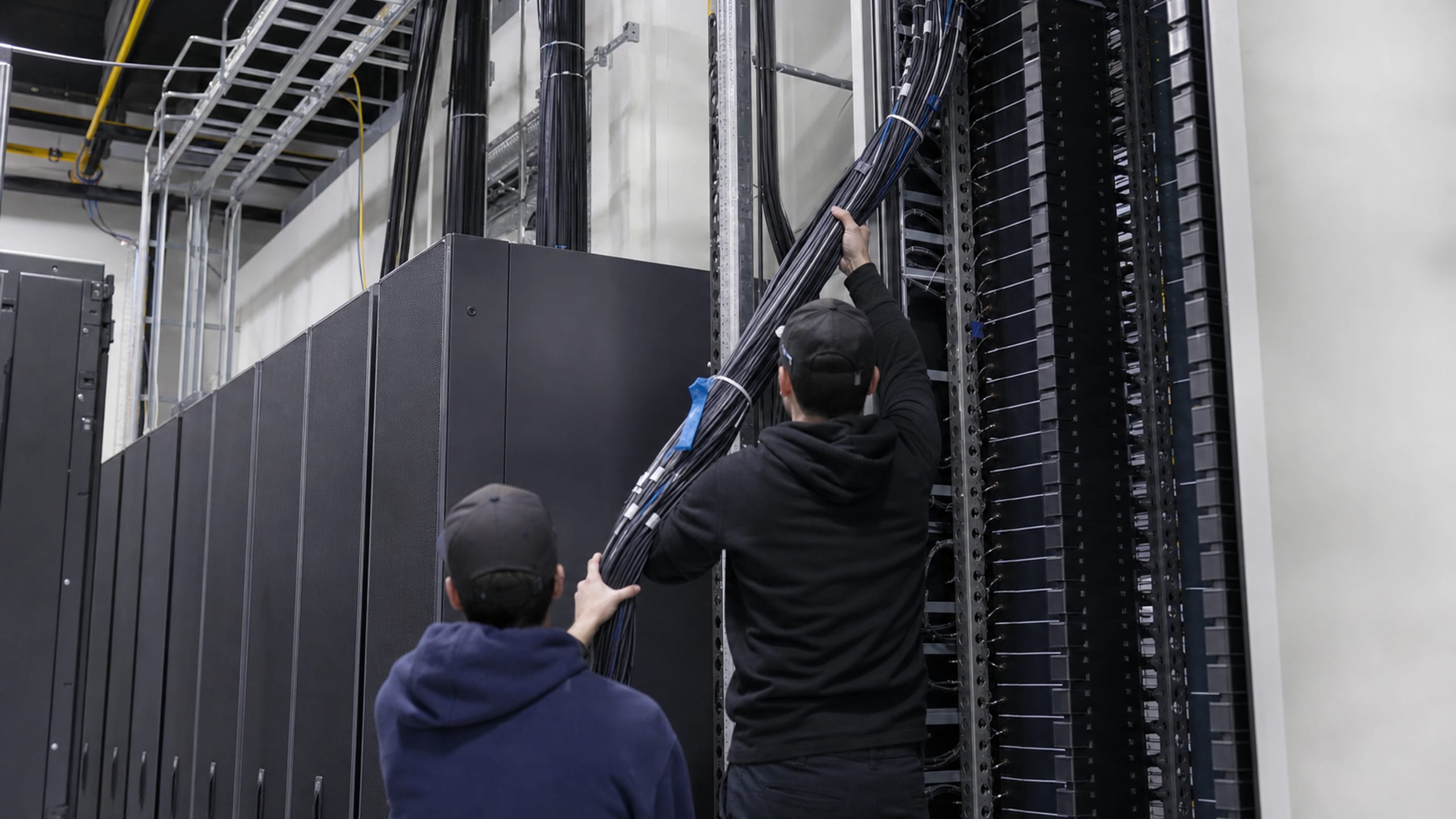
Every project starts from a site survey: the pathways that already exist, the pathways that have to be built, the telecom-room and rack layout, and the cable counts a multi-year growth projection actually needs. Getting the counts and the routes right on paper is what spares a live building from a second construction project a year later — the one rework a cabling design can rarely absorb.
From there we pull, dress, terminate and label copper and fiber to the ANSI/TIA-568 family, run the pathways and spaces to TIA-569-E, bond and ground the plant to TIA-607, and certify every run — so the plant that is handed over stands on a known-good, documented baseline rather than a bundle of untested cable behind a patch panel.
Site survey first — pathways, spaces, cable counts and the standards the facility follows
Copper and fiber pulled, dressed, terminated and labeled to ANSI/TIA-568 and TIA-606
Bonding and grounding to TIA-607; installation to the ANSI/BICSI N1-2019 standard
Certified link/channel test results delivered with the as-builts
Structured cabling, the rooms and racks it lands in, the carrier handoff, the legacy cable it replaces and the adjacent systems that share the pathway — scoped together against a single site survey.
Each scope is set against the site survey and delivered to the same standard — installed to the ANSI/TIA-568 family and the ANSI/BICSI N1-2019 practices, labeled to TIA-606 and certified before handover.
Structured cabling & fiber backbone
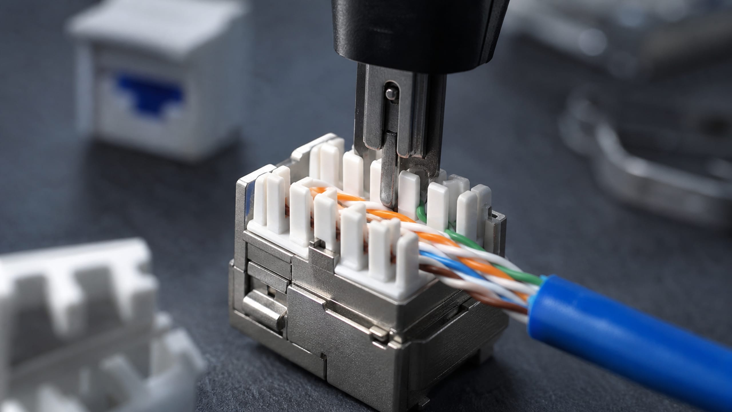
Horizontal and backbone cabling is installed to the ANSI/TIA-568 family, which defines the twisted-pair categories — Cat3, Cat5e, Cat6, Cat6A on up through Cat8 — and the OM multimode and OS singlemode fiber classes. Copper is specified to the channel it has to carry: Category 6A supports 500 MHz and the full 10GBASE-T channel at the standard 100-meter length, where standard Category 6 (250 MHz) cannot reliably reach it — so a floor that has to run 10-Gigabit to the desk gets Cat6A rather than a category that will be re-pulled at the next refresh.
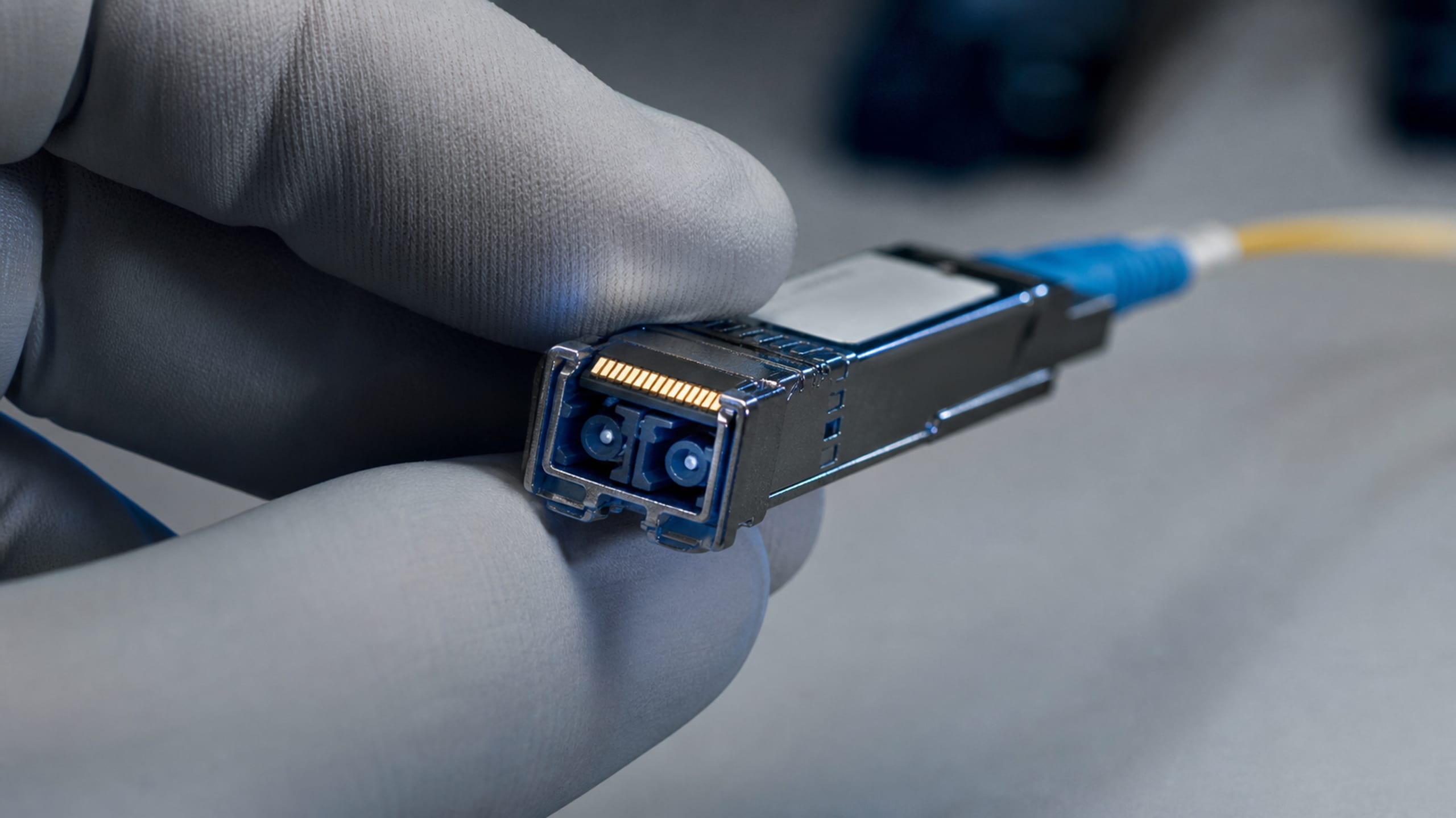
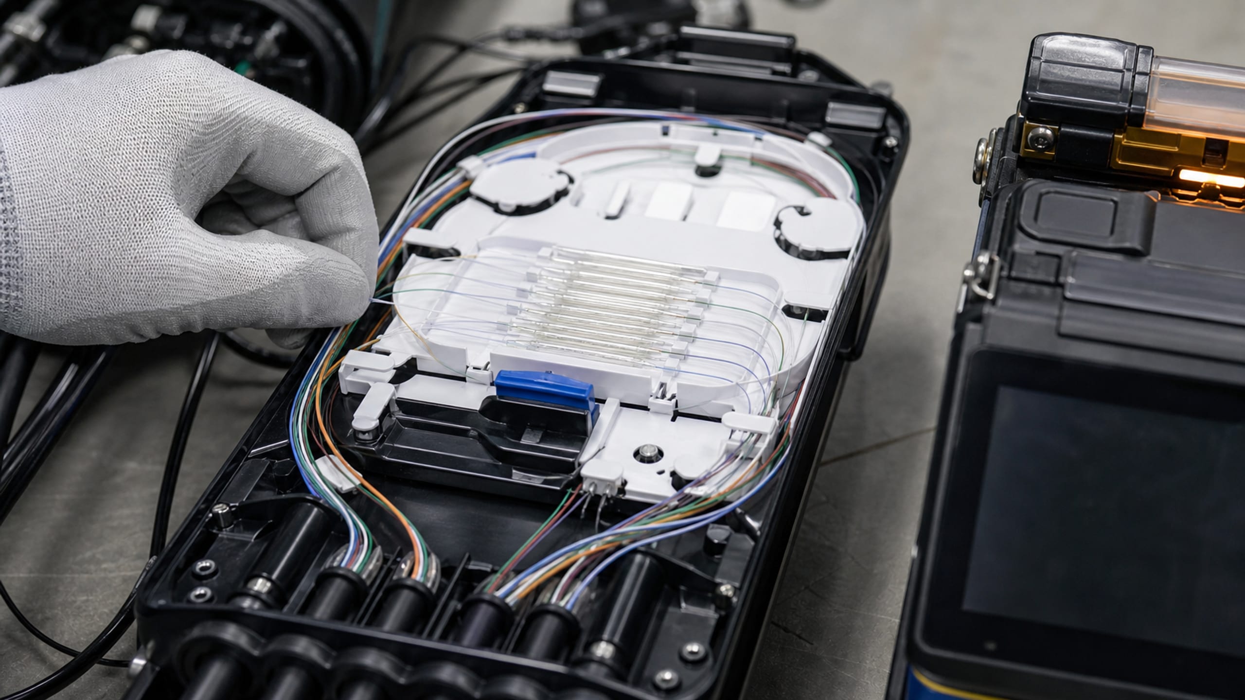
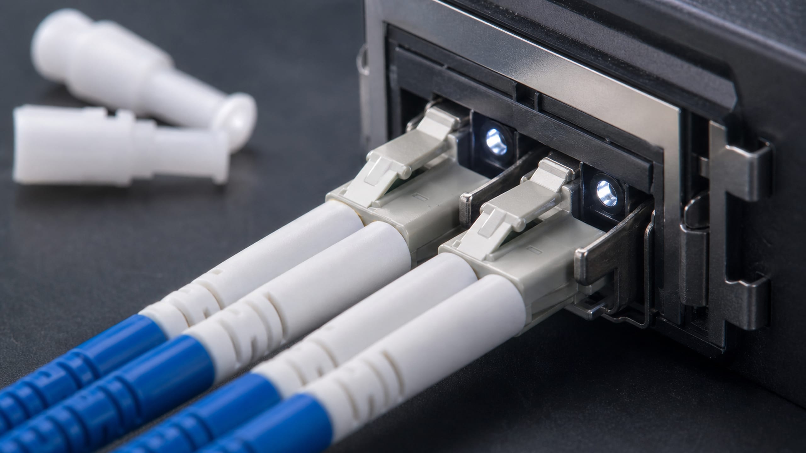
The fiber backbone is planned the same way. OS2 low-water-peak singlemode is the standard for campus backbones, WAN links and any run over 300 meters; OM4 laser-optimized 50-micron multimode carries 10-Gigabit Ethernet to 550 meters for in-building backbone — the OM/OS nomenclature TIA adopted from ISO/IEC 11801 in ANSI/TIA-568.3-D. Fiber is terminated and fusion-spliced, copper is punched down to the pinout, and every link is certified so the plant is proven, not assumed.
Cat6 / Cat6A twisted-pair horizontal to ANSI/TIA-568 (Cat6A for full-channel 10GBASE-T)
OS2 singlemode and OM4 multimode fiber backbone sized to distance and capacity
Fusion splicing, LC/SC fiber termination and copper punch-down to the pinout
Certified link/channel test results per run as a cabling deliverable
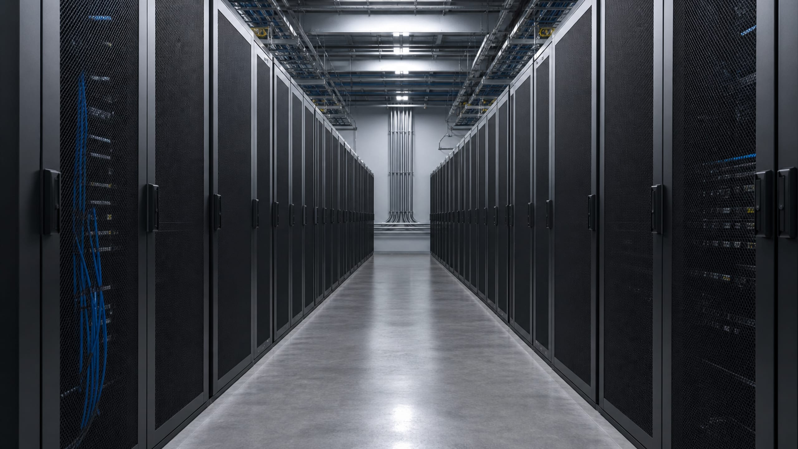
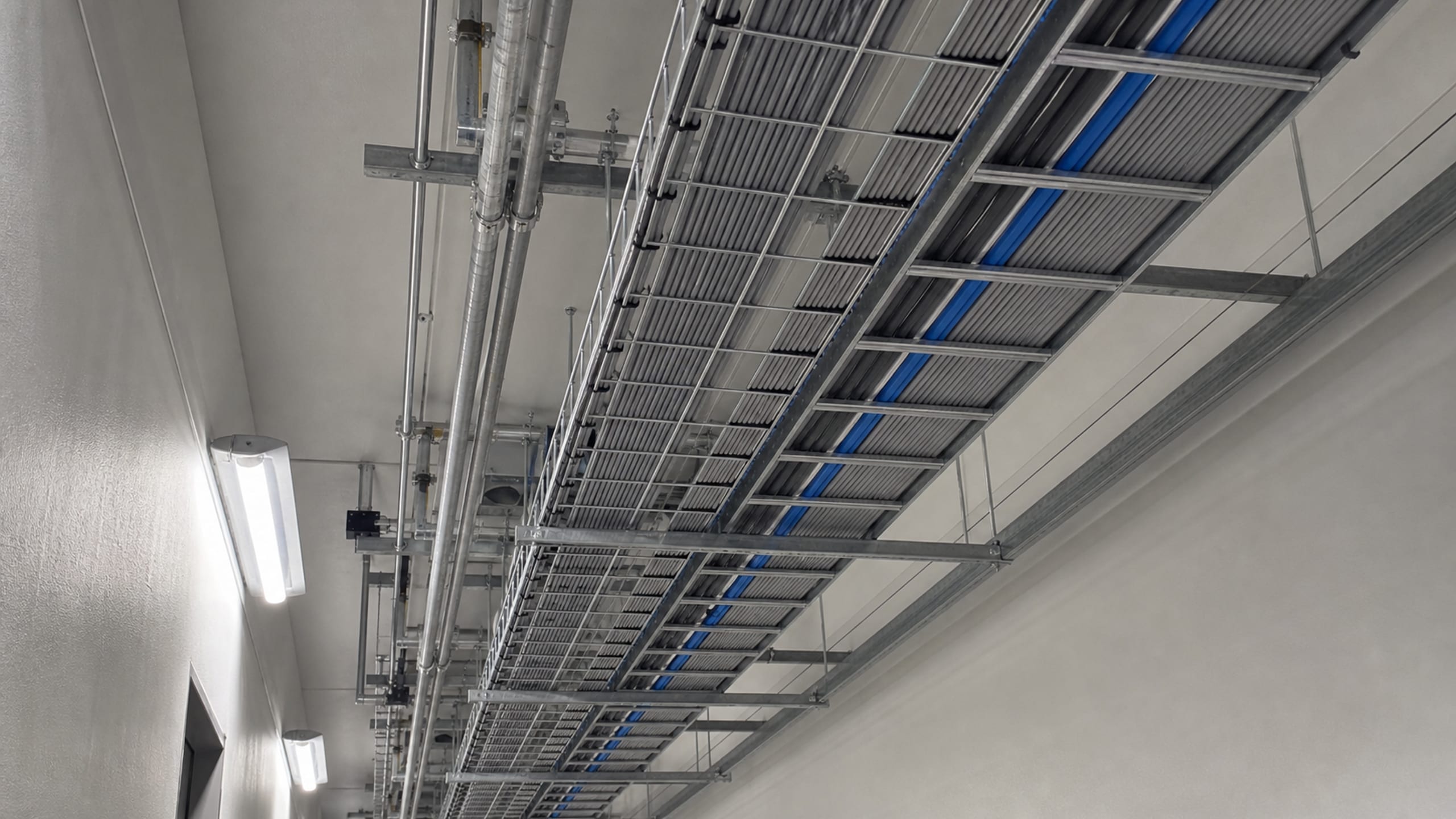
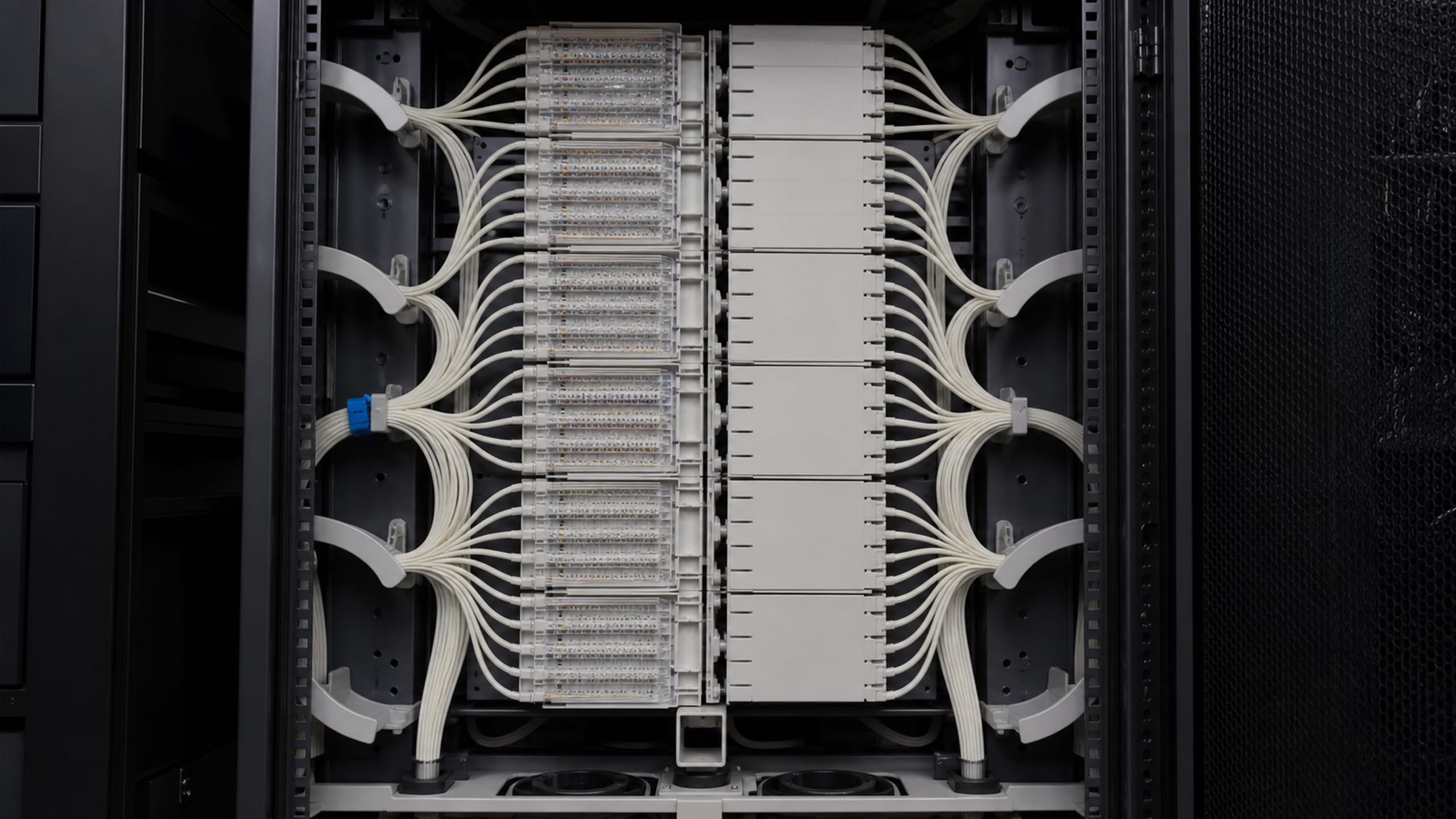
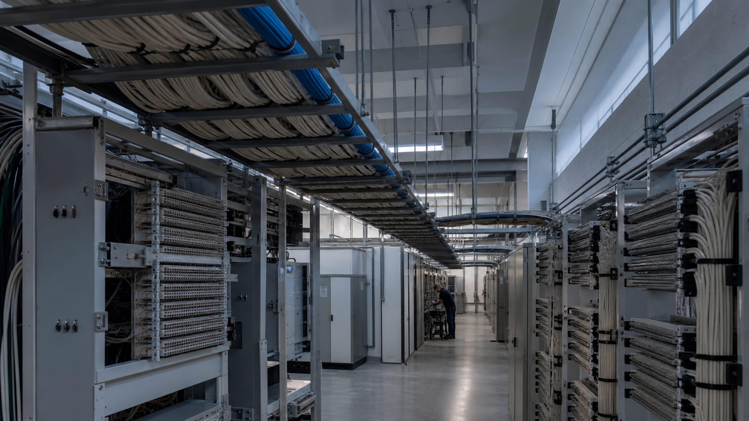
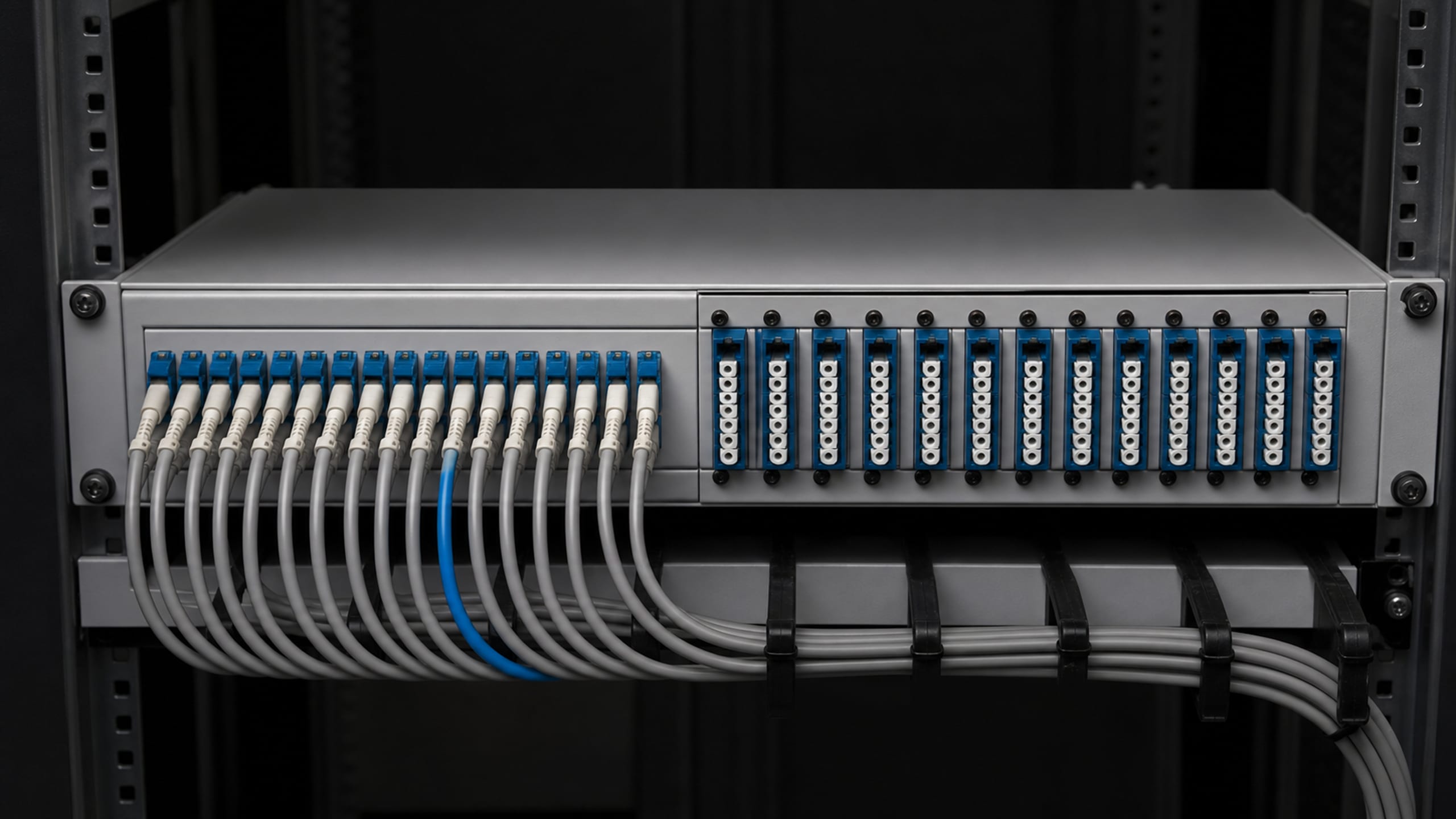
The main and intermediate distribution frames — the equipment rooms and telecommunications rooms where the plant lands — are built to TIA-569-E, the standard that governs the pathways and spaces: the conduits, cable trays and J-hooks that carry the cable and the rooms that house it. Racks, ladder rack, patch panels and vertical and horizontal cable management are installed so the room is serviceable on day one and still legible after a hundred moves, adds and changes.
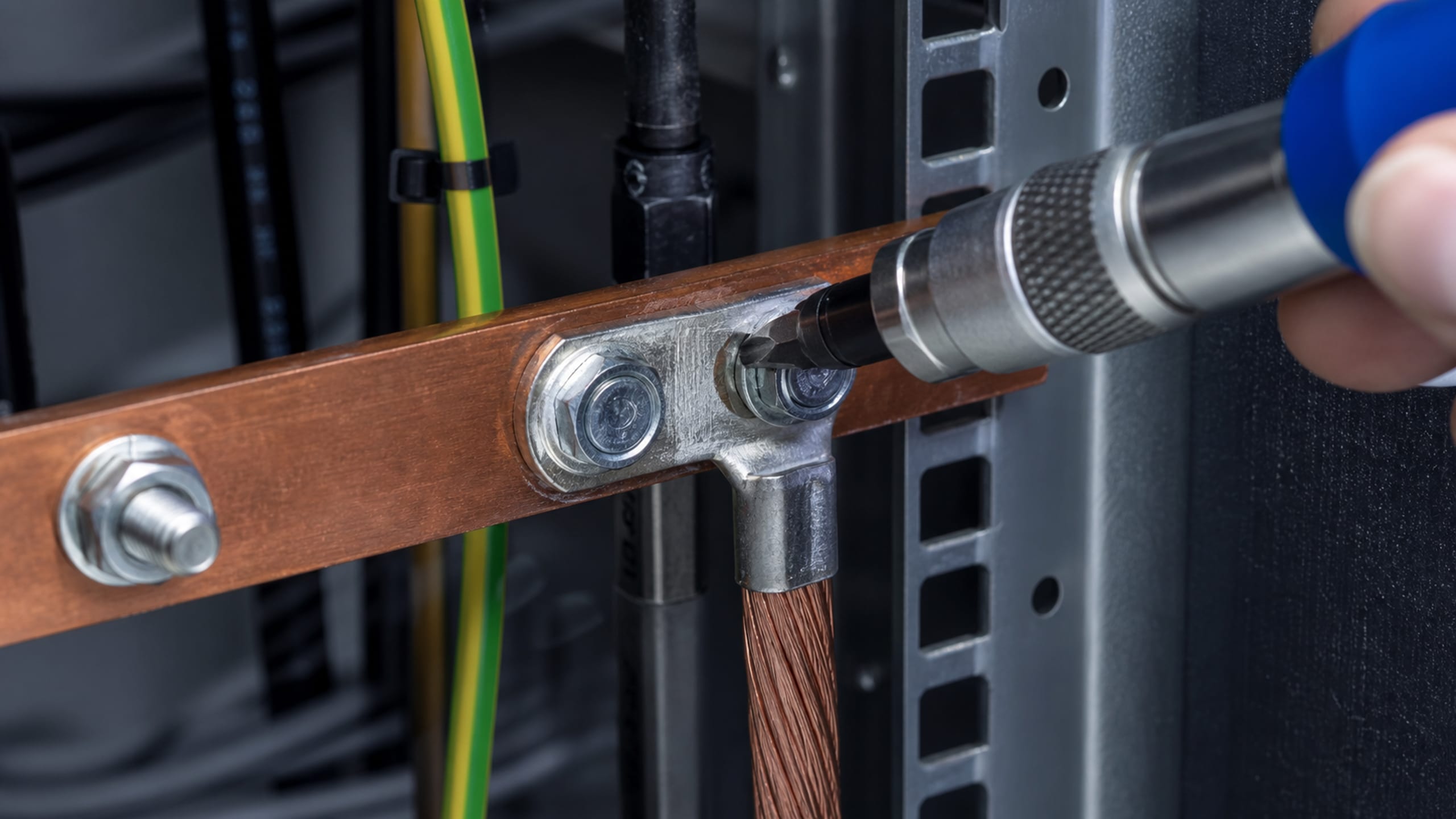
Bonding and grounding are built in, not added after the network starts throwing errors. TIA-607 requires racks, enclosures, cable trays, ladders, surge protectors and patch panels to be bonded to a telecommunications grounding busbar; we install the busbar system it defines — the Telecommunications Main Grounding Busbar (TMGB), the Telecommunications Grounding Busbars (TGB) and the Telecommunications Bonding Backbone (TBB) — with bonding conductors sized to the standard's minimum of 6 AWG.
MDF/IDF fit-out — equipment rooms and telecom rooms to TIA-569-E
Rack, ladder-rack, patch-panel and cable-management buildout
TIA-607 bonding and grounding — TMGB, TGB and TBB, minimum 6 AWG
Labeling and administration to TIA-606-D across the frame
A carrier circuit lands at the demarcation point or minimum point of entry (MPOE) and stops there — the run from that point to the equipment room is inside wiring, and it is the customer's to build. We extend the demarc: the entrance-facility and point-of-presence (POP) pathway, the cross-connects, and the inside cabling that carries the circuit from where it enters the building to the rack that terminates it.
For leased-line and dedicated-internet-access (DIA) turn-ups we coordinate with the serving carrier around the physical hand-off — the demarc location, the cross-connect and the inside wiring the carrier's tester needs on the day of turn-up — so the circuit lights on the scheduled date instead of stalling on a missing extension. Communications circuits entering the building are installed under NEC Article 800, including its grounding requirements and the required separation from power and lighting conductors.
Demarc / MPOE extension and inside wiring to the equipment room
Entrance-facility and POP pathway with carrier cross-connects
Carrier coordination for leased-line and DIA circuit turn-up
Entrance grounding and power separation to NEC Article 800
Cable-plant removal & abandoned-cable abatement
Decades of refreshes leave a building's trays and plenums packed with cable that no longer goes anywhere, and the code treats it as a fire-load problem. NEC 800.25 requires the accessible portion of abandoned communications cable to be removed — where 'abandoned cable' is cable that is not terminated at both ends at a connector or equipment and not identified with a tag for future use. A durable tag is the code-accepted alternative to removal, and 'accessible' means what can be removed or exposed without damaging the building's structure or finish, so cable concealed inside a finished wall is not required to come out.
We survey the existing plant against that definition, then remove or tag accordingly — reclaiming tray and pathway capacity for the new cabling so the incoming plant is installed in clear pathway rather than layered on top of a decade of dead cable.
Accessible abandoned communications cable removed per NEC 800.25
Tag-for-future-use applied where the code permits it in place of removal
Concealed-in-wall exclusion honored — no destructive demolition
Tray and pathway capacity reclaimed for the incoming plant
Adjacent low-voltage systems cabling
The same cabling discipline extends to the building's other low-voltage systems that share the pathway: paging and intercom, CATV/MATV, distributed-antenna-system (DAS) coax and fiber, and the device cabling for IP cameras and access-control readers and locks. These are power-limited Class 2 and Class 3 circuits under NEC Article 725 and, where fiber is used, NEC Article 770 — pulled, terminated and labeled to the same standard as the data plant, with the required separation from power and lighting conductors kept throughout.
This lane installs and documents the cabling and the pathway; the head-end systems those cables serve — the video-management and physical-access platforms, the DAS head-end — are designed, integrated and commissioned in Uniqcli's access control and cybersecurity lanes, so one accountable relationship carries the pathway and the systems that ride it.
Paging/intercom, CATV/MATV and DAS coax and fiber cabling
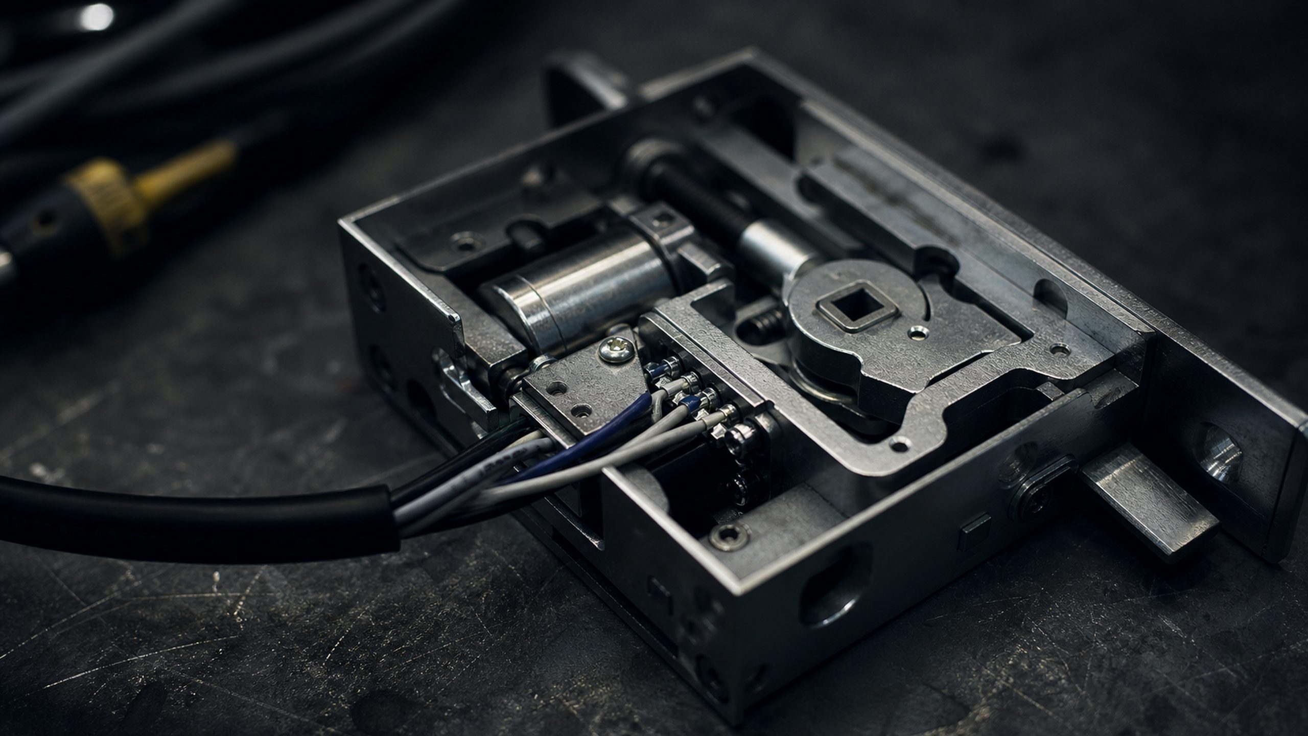
IP camera and access-control reader and lock device cabling
Class 2/3 (NEC Art. 725) and fiber (Art. 770) with power separation maintained
Head-end design handed to the access control and cybersecurity lanes
Standards
Built and documented to the codes the facility answers to
Low-voltage cabling lives at the intersection of a performance standard and an electrical code. The performance side is the ANSI/TIA-568 family — the twisted-pair categories from Cat3 through Cat8 and the OM multimode and OS singlemode fiber classes it defines — installed to ANSI/BICSI N1-2019, the ANSI-approved installation standard that replaced the withdrawn NECA/BICSI 568, and designed against the BICSI Telecommunications Distribution Methods Manual (the TDMM), the ICT industry's cornerstone design reference and the basis for the RCDD designation. Pathways and spaces follow TIA-569-E, labeling and record-keeping follow TIA-606-D, and bonding and grounding follow TIA-607.
The code side is the National Electrical Code: communications circuits under Article 800, power-limited Class 2 and Class 3 signaling under Article 725, and optical-fiber cabling under Article 770 — including the required separation from power and lighting conductors and the removal of accessible abandoned cable under NEC 800.25. These are the practices the installation follows; the jurisdiction-specific low-voltage licensing and permitting for a given site are confirmed during the survey rather than assumed.
ANSI/TIA-568 copper (Cat3–Cat8) and OM/OS fiber, terminated and tested to spec
TIA-569-E pathways and spaces; TIA-606-D labeling and as-built administration
Which cabling categories and fiber types do you install?
Copper and fiber to the ANSI/TIA-568 family. On copper we install Cat6 and Cat6A — Cat6A where a run has to carry the full 10GBASE-T channel at 100 meters, which standard Cat6 cannot reliably do. On fiber we install OS2 singlemode for campus backbones, WAN links and runs over 300 meters, and OM4 multimode for in-building backbone (10-Gigabit Ethernet to 550 meters). The right mix is set against the site survey and the speeds the plant has to carry now and after the next refresh.
Do you remove abandoned or legacy cable?
Yes. NEC 800.25 requires the accessible portion of abandoned communications cable to be removed — cable that isn't terminated at both ends and isn't tagged for future use. A durable tag is the code-accepted alternative to removal, and cable concealed inside a finished wall isn't required to come out. We survey the plant against that definition, remove or tag accordingly, and reclaim the tray and pathway capacity for the new cabling. Scope is quoted per the site survey.
Are you licensed, and do you hold a BICSI RCDD?
Cabling is designed against the BICSI Telecommunications Distribution Methods Manual and installed to the ANSI/BICSI N1-2019 standard and the ANSI/TIA-568 family; those are the practice references the work follows. The jurisdiction-specific low-voltage licensing and permitting for a given site are confirmed during the survey for that project rather than assumed, so the scope reflects what the location actually requires.
How is the installed plant documented?
To TIA-606-D — the administration standard for labeling and record documentation. Every run is labeled at both ends, the plant is captured in as-built records, and certified link and channel test results are delivered per run, so warranty and future moves, adds and changes start from a known-good baseline instead of guesswork.
Can you coordinate a carrier circuit and extend the demarc?
Yes. We extend the circuit from the demarcation point or MPOE to the equipment room — the entrance-facility and POP pathway, the cross-connects and the inside wiring — and coordinate with the serving carrier around the physical hand-off for leased-line and DIA turn-ups so the circuit lights on the scheduled date. The entrance work follows NEC Article 800 for grounding and separation from power.
How an engagement runs
From requirement to delivered, in four steps
1
Brief
Send the requirement as it exists: a statement of work, drawings, a bill of materials or a problem statement. A briefing call scopes it against the lines above.
2
Scope and quote
Feasibility, country-of-origin and §889 screening, and lead times come back with a line-item quote. Nothing is committed until the scope is agreed.
3
Build and integrate
Manufacture, rack, image, configure and test in the facility, so the first time the system is assembled is not on install day.
4
Deliver and sustain
Delivery with serialized chain-of-custody records, then warranty, RMA and lifecycle support on the same relationship.
Compliance and documentation
Screened before it is quoted, documented when it ships
Country of origin and §889 status are checked per line while the quote is being built, not after a program review asks. The same record travels with the order: what was sourced, where it came from, who handled it and when it shipped.
TAA (FAR 52.225-5) country-of-origin screening on every line
NDAA §889 covered-equipment screening on every line
FIPS 140-2/3 validated options where the requirement calls for it
DoDIN APL listing paths verified before a quote is issued
Section 508 / VPAT documentation available on request
Serialized chain-of-custody records delivered with every shipment
Send a floor plan, a rack elevation, or just ask for the walk. Scope is quoted against what the survey finds — with the cabling design, the standards it is built to and the test plan alongside it.