
Ethernet Cable Length Limits and Cable Picker
How far each media type is rated to carry 1G through 100G — and the cables we stock at that length.
The short answer: a copper Ethernet run is rated to 100 meters (328 feet) per channel from Cat5e through Cat6a — and Cat6 only carries 10G to 55 meters. Past that, the fixes are a switch or extender mid-run, or fiber, which carries the same speeds for hundreds of meters to 10 kilometers depending on the module.
Link planner
Will it reach?
Enter the link speed and the length of the actual cable route — the path it takes through walls and trays, not the straight line. We show which media are rated to carry it, then filter the cables below to match.
Cat6a copper carries 10 GbE over this run
Rated reaches at this speed — anything marked Works has published headroom for the run you entered.
- Cat5e copper—Not rated
- Cat6 copper37–55 mWorks
- Cat6a copper100 m (328 ft)Works
- DAC — passive twinaxup to 7 mToo far
- AOC — active optical1–30 m typicalWorks
- OM3 multimode fiber300 mWorks
- OM4 multimode fiber400 mWorks
- OS2 single-mode fiber10 kmWorks
Filters to cables at least as long as the run — add slack for the route and the service loop.
Or jump to a length:
Showing 24 of 48,480 cables
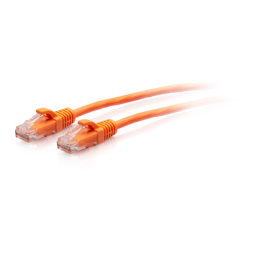
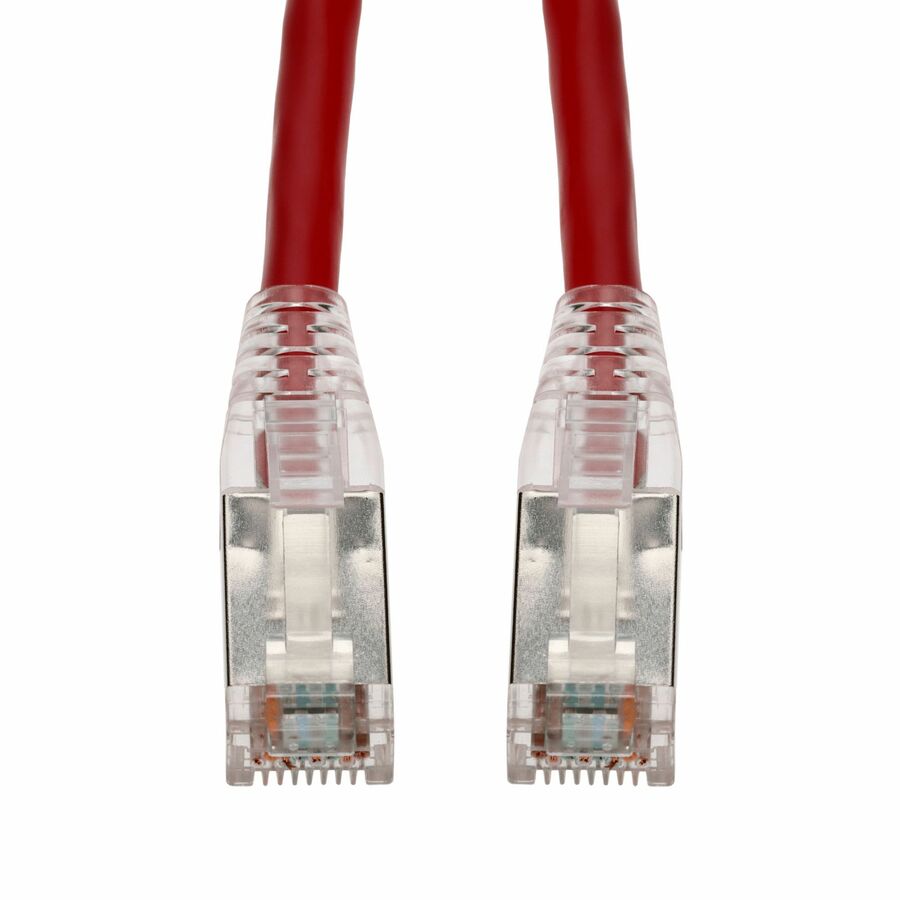
- Axiom Memory SolutionsAxiom 25FT CAT6A BENDnFLEX Ultra-Thin Snagless Patch Cable 650mhz (Black) - 25 ft Category 6a Network Cable for Network Device - First End: 1 x RJ-45 Network - Male - Second End: 1 x RJ-45 Network - Male - 10 Gbit/s - Patch Cable - Shielding - Gold Plated Contact - 28 AWG - Black - TAA CompliantC6ABFSB-K25-AX
$28.00
$26.71
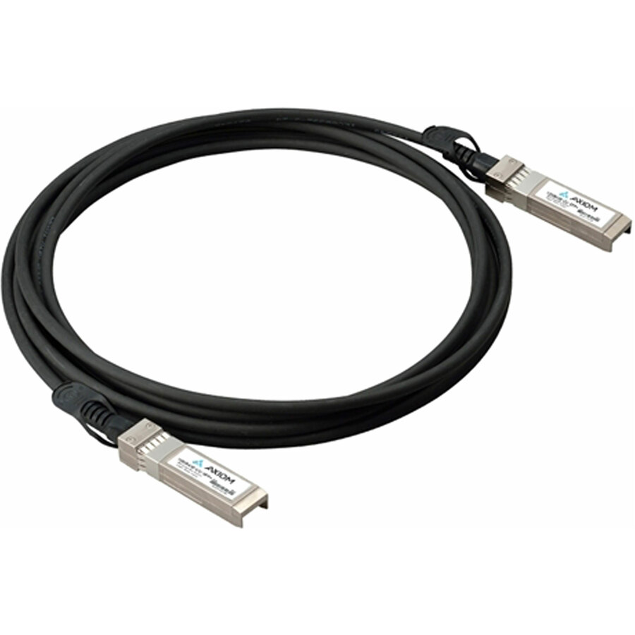
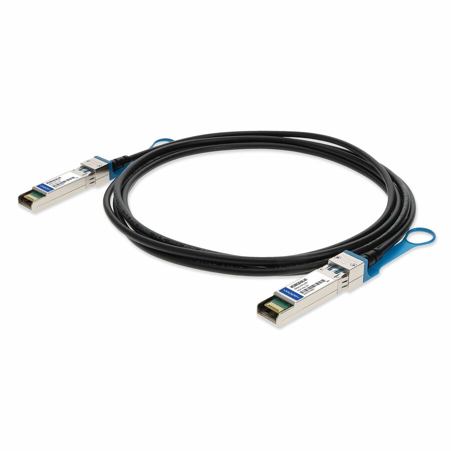
48 in stock - AddOnAddOn Mellanox® MC3309130-0A1 Compatible TAA Compliant 10GBase-CU SFP+ Direct Attach Cable (Passive Twinax, 1.5m) - 4.92 ft Twinaxial Network Cable for Network Device - First End: 1 x SFP+ Network - Second End: 1 x SFP+ Network - 10 Gbit/s - 30 AWG - Black - 1.0 - TAA CompliantMC3309130-0A1-AO
$32.00
$29.44
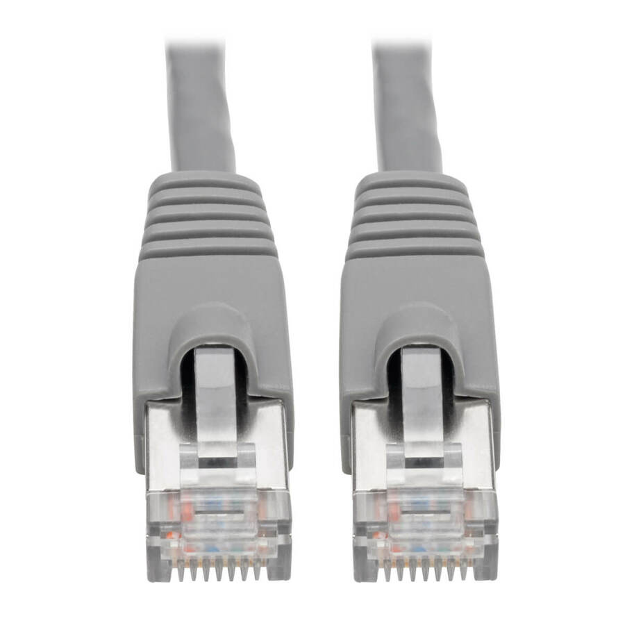
111 in stock - EatonTripp Lite by Eaton Cat6a 10G Snagless Shielded STP Ethernet Cable (RJ45 M/M) PoE Blue 7 ft. (2.13 m) - 7 ft Category 6a Network Cable for Network Device - First End: 1 x RJ-45 Network - Male - Second End: 1 x RJ-45 Network - Male - 10 Gbit/s - Patch Cable - Shielding - 26 AWG - BlueN262-007-BL
$23.65
$21.76
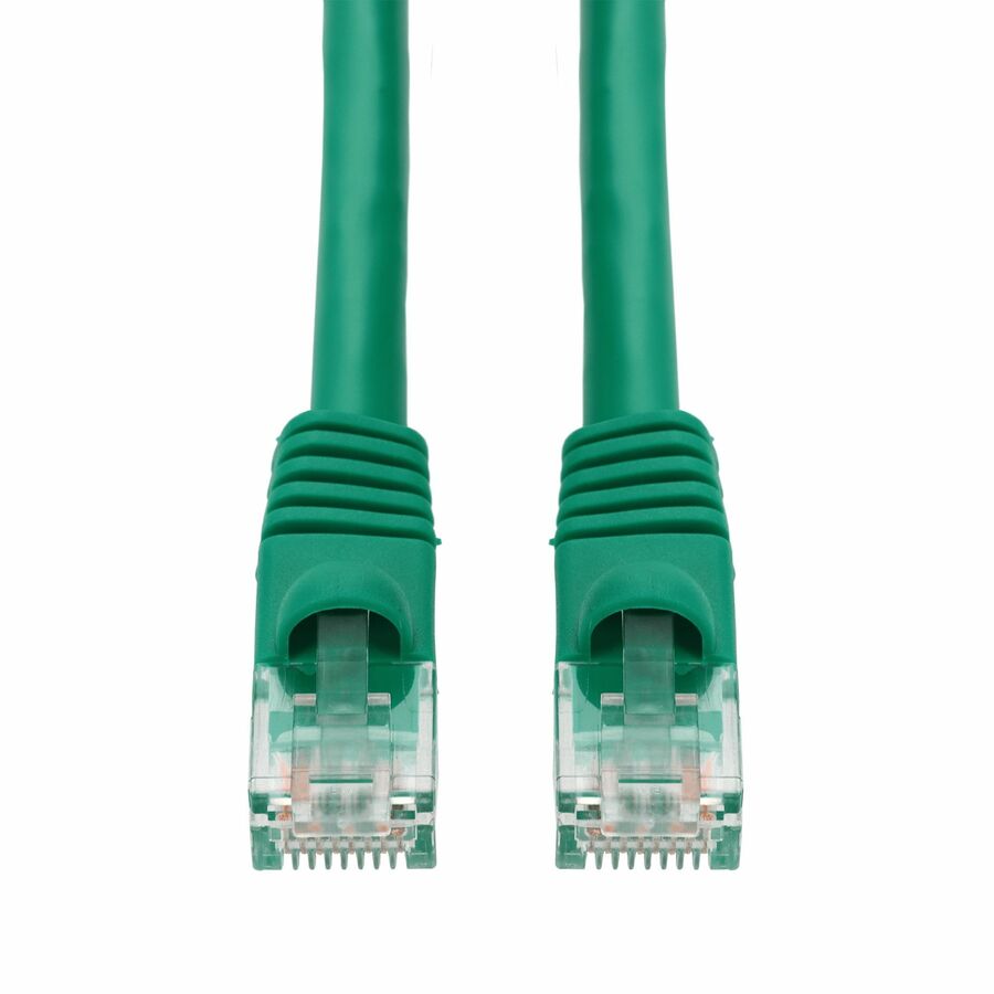
2,241 in stock - AddOnAddOn 2.5ft Green CAT 6 PVC Ethernet Cable Snagless Bubble Boot RJ-45 M/M - 2.50 ft Category 6 Network Cable for Network Device - First End: 1 x RJ-45 Network - Male - Second End: 1 x RJ-45 Network - Male - Patch Cable - Unshielded Twisted Pair (UTP) - CM - 24 AWG - Green - 1 PieceADD-2-5FCAT6-GN
$23.50
$21.62
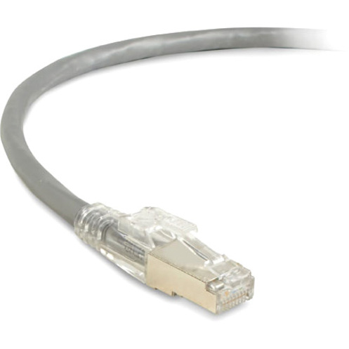
49 in stock - Black BoxBlack Box GigaTrue 3 Cat.6 (S/FTP) Patch Network Cable - 7 ft Category 6 Network Cable for Patch Panel, Wallplate, Network Device - First End: 1 x RJ-45 Network - Male - Second End: 1 x RJ-45 Network - Male - 1 Gbit/s - Patch Cable - Shielding - Gold Plated Contact - CM - 24 AWG - GrayC6PC70S-GY-07
$23.71
$20.34
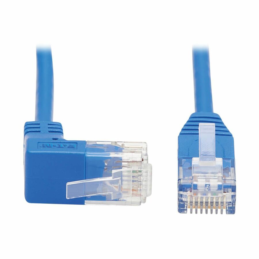
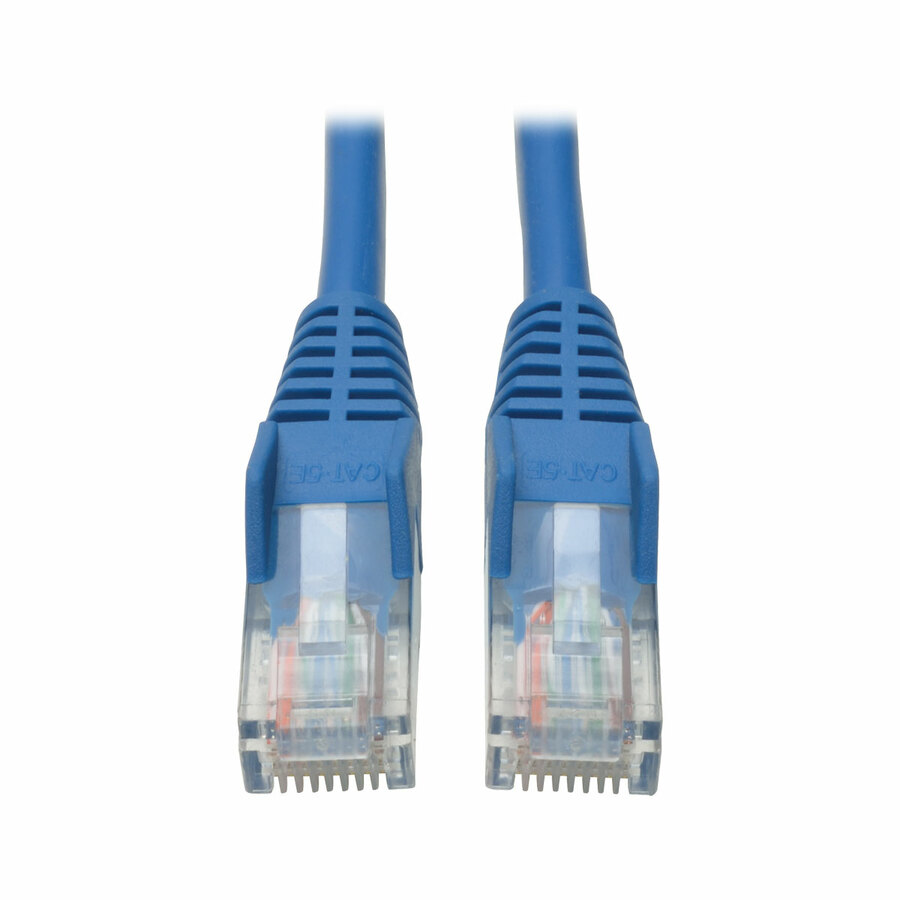
386 in stock - EatonEaton Tripp Lite Series Cat5e 350 MHz Snagless Molded (UTP) Ethernet Cable (RJ45 M/M), PoE - Blue, 40 ft. (12.19 m) - 40 ft Category 5e Network Cable for Network Device - First End: 1 x RJ-45 Network - Male - Second End: 1 x RJ-45 Network - Male - Patch Cable - BlueN001-040-BL
$29.64
$27.27
615 in stock
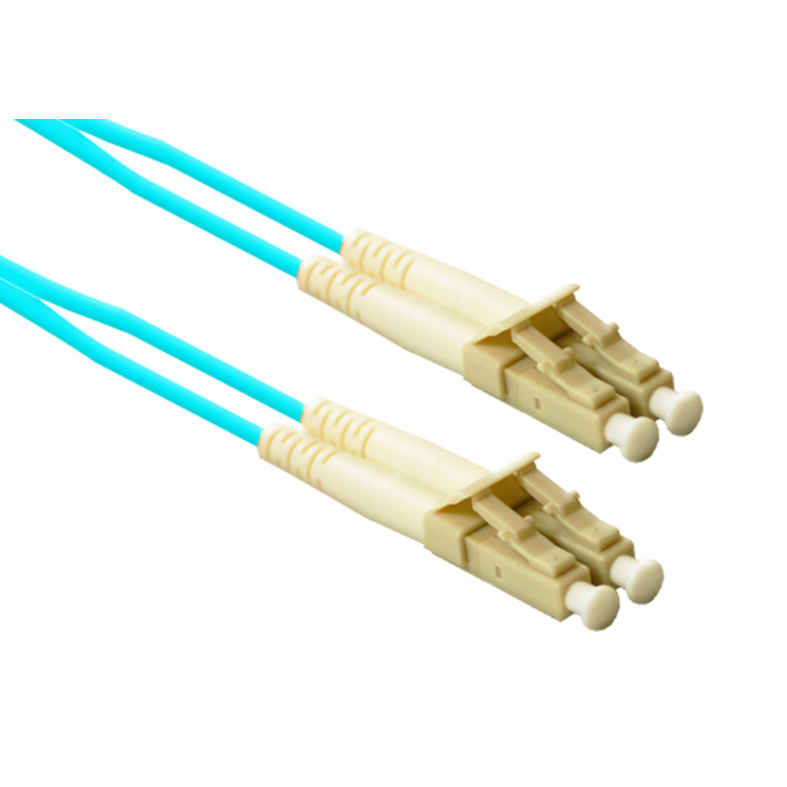
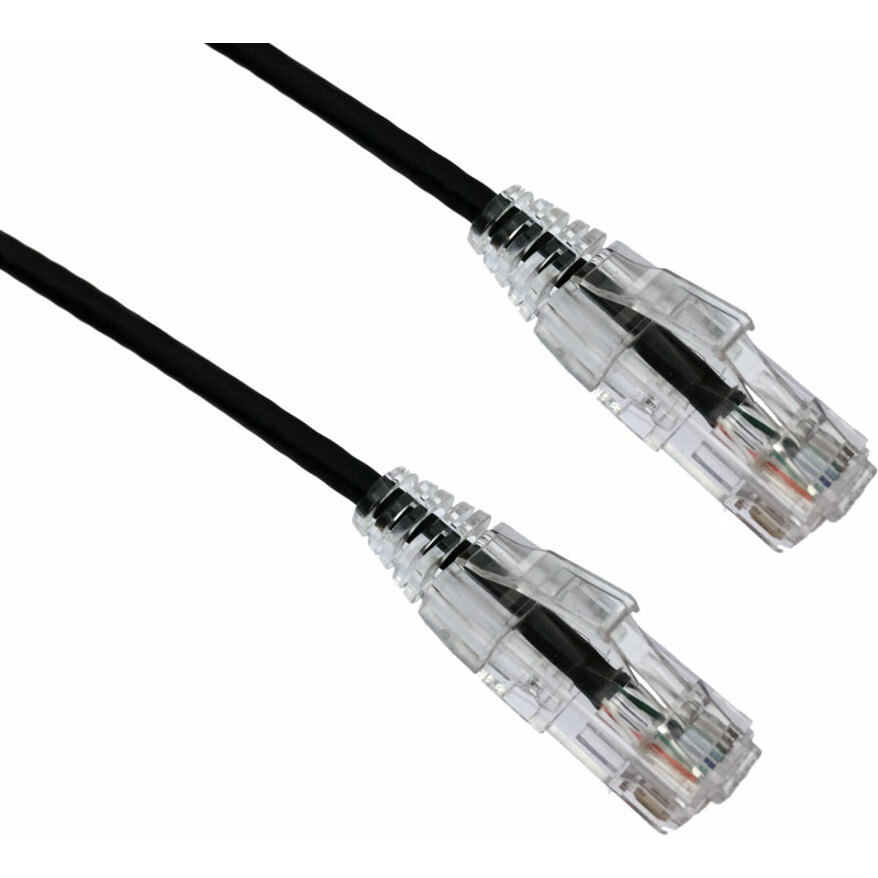
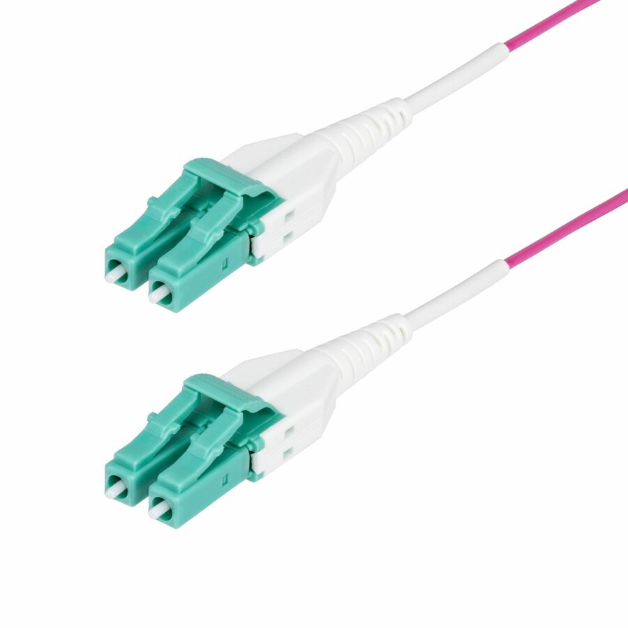
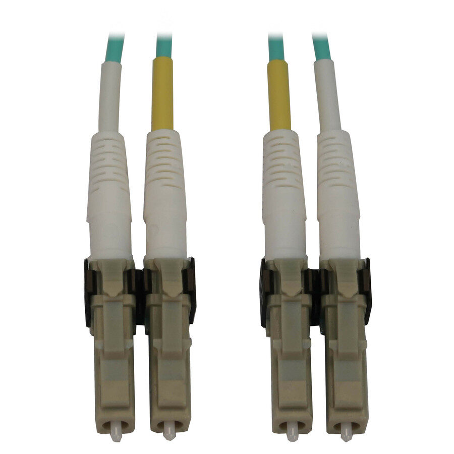
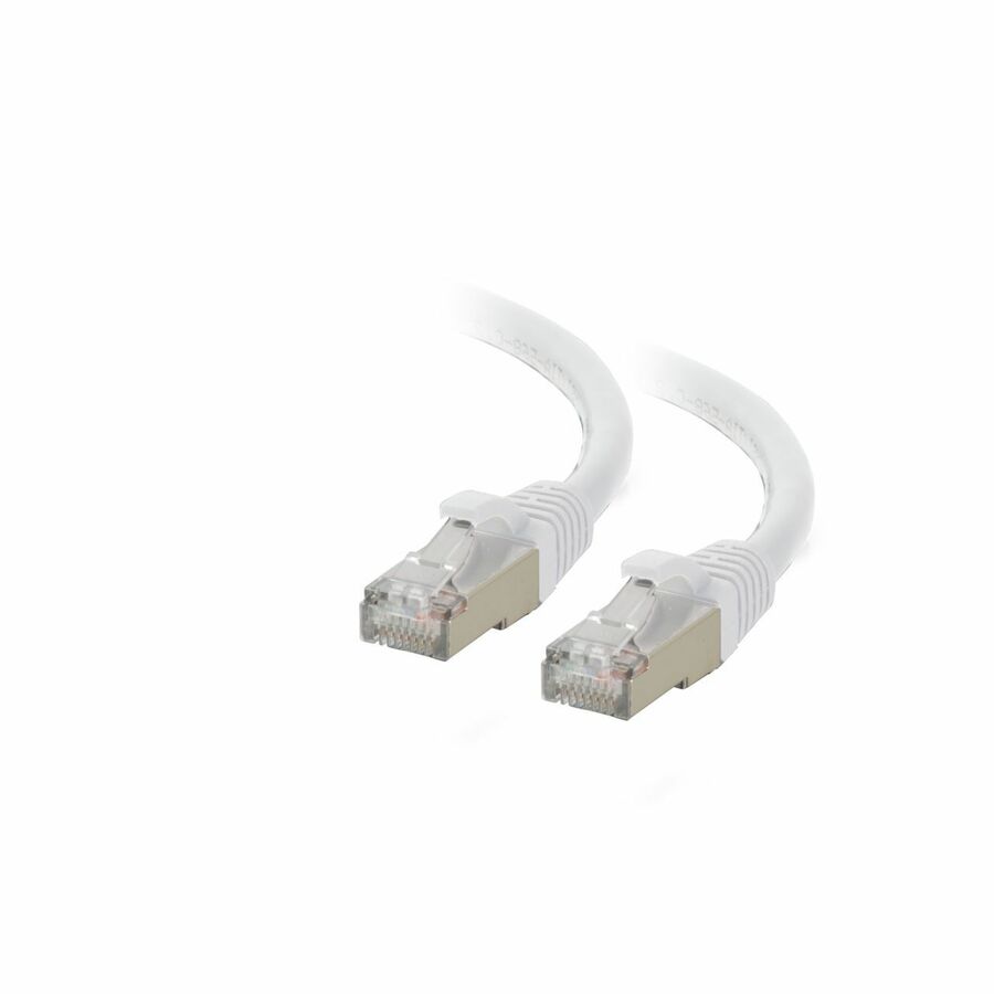
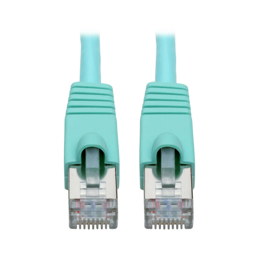
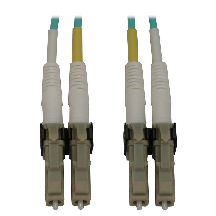
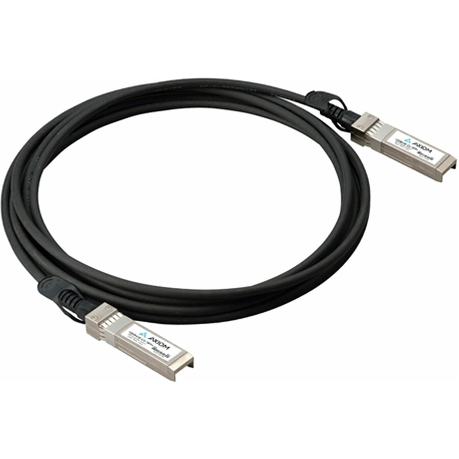
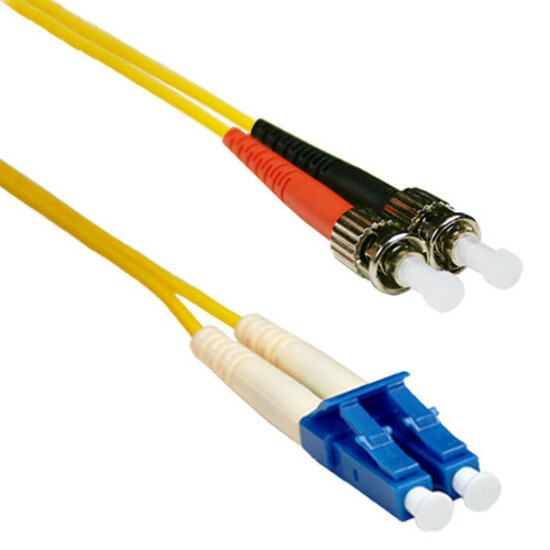
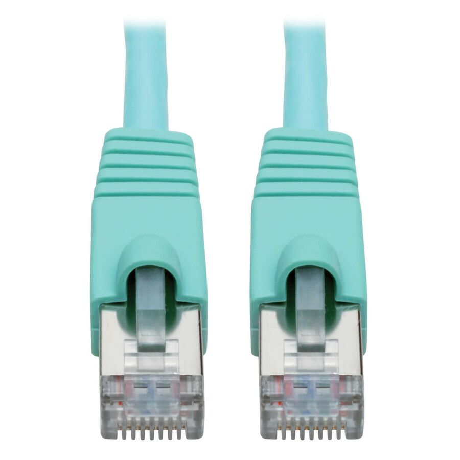
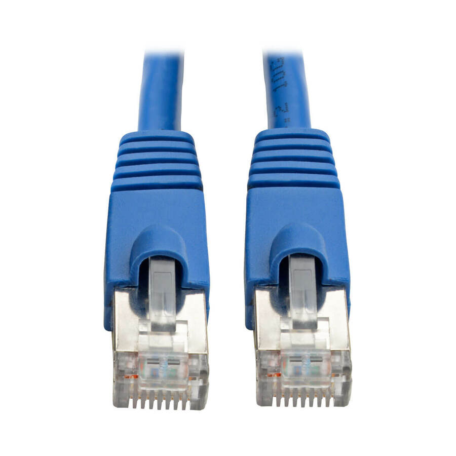
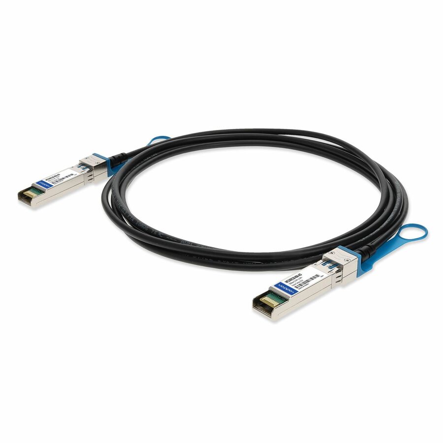
Specifications are read from the manufacturer product title as supplied to us; where a value is not stated it is left blank rather than estimated. Every line is screened for NDAA §889 status before checkout, with TAA verified on request.
Reference
Maximum cable length by media type and speed
The familiar 100 meter (328 foot) Ethernet limit is a channel budget rather than a property of the cable: ANSI/TIA-568 allows 90 meters of fixed horizontal cable plus up to 10 meters of patch cords across both ends. Every other figure below comes from the IEEE 802.3 clause that defines the physical layer in question — with the single exception of the AOC row, which is vendor-specified and footnoted as such — so the number changes with the speed you are running, not with the brand on the jacket.
| Cable / media | 1 GbE | 10 GbE | 25 GbE | 40 GbE | 100 GbE |
|---|---|---|---|---|---|
| Cat5e copper | 100 m (328 ft) | — | — | — | — |
| Cat6 copper | 100 m (328 ft) | 37–55 m | — | — | — |
| Cat6a copper | 100 m (328 ft) | 100 m (328 ft) | — | — | — |
| DAC — passive twinax | — | up to 7 m | up to 5 m | up to 7 m | up to 5 m |
| AOC — active optical | — | 1–30 m typical | 1–30 m typical | 1–30 m typical | 1–30 m typical |
| OM3 multimode fiber | 550 m | 300 m | 70 m | 100 m | 70 m |
| OM4 multimode fiber | 550 m | 400 m | 100 m | 150 m | 100 m |
| OS2 single-mode fiber | 5 km | 10 km | 10 km | 10 km | 10 km |
- Cat6 at 10 Gigabit: TIA TSB-155-A gives 37 meters in the worst alien-crosstalk case and up to 55 meters once crosstalk is mitigated. Treat anything past 37 meters as a link that needs a survey, or specify Cat6a.
- AOC is the one row above that is not an IEEE figure: active optical assemblies are vendor-specified, and real 10G through 100G parts range from about 1 to 30 meters depending on the maker. The 1–30 m shown is typical rather than rated — check the reach on the specific part before you commit a run to it.
- 100 Gigabit multimode: the table uses today's 100GBASE-SR4 QSFP28 figures (70 m on OM3, 100 m on OM4). The older 100GBASE-SR10 parallel optics reached 100 m and 150 m, which is what most third-party tables still print.
- 2.5GBASE-T and 5GBASE-T (IEEE 802.3bz) run the full 100 meters on existing Cat5e and Cat6 — the reason a building does not need re-cabling to get past 1 Gigabit.
- 25GBASE-T and 40GBASE-T over Cat8 reach 30 meters on a two-connector channel. That is a top-of-rack option rather than a building cable; we quote it on request.
- Power over Ethernet does not change the length limit — 100 meters still applies. What changes with length is voltage drop, which is why an 802.3bt source budgets more power than the device at the far end receives.
For ordinary twisted-pair Ethernet, the familiar maximum is a 100-meter channel—328 feet—including the permanent cable and patch cords at both ends. That answer changes with the Ethernet speed and media. Cat6 supports 1GbE for the full channel but needs assessment for 10GBASE-T beyond the shorter installed-cabling range; Cat6a supports 10GBASE-T for the full 100-meter channel. Fiber, DAC, and active optical assemblies use different limits. Start with speed and measured route distance, then choose the medium.
Key takeaways
- A 100-meter Ethernet limit is a channel budget, not permission to install 100 meters of permanent cable and then add patch cords.
- The permanent horizontal link is normally planned to 90 meters, leaving the rest of the channel allowance for patching at the work area and equipment room.
- Cat6 can carry 10GbE only over a shorter, installation-dependent reach; Cat6a is the normal full-channel choice for 10GBASE-T.
- Fiber is the right answer when the run exceeds copper reach, crosses buildings or electrical environments, or must carry higher speeds beyond a rack row.
- Measure the routed path, include service loops and patching, and certify installed structured cabling to the application—not just the jacket category.
The short answer by common use case
1GbE over Cat5e, Cat6, or Cat6a: Up to a 100 m channel when the installed link and patch cords meet the applicable standard
2.5GbE or 5GbE over supported installed copper: Often designed for a 100 m channel on qualifying Cat5e/Cat6 plant; validate the installed channel
10GbE over Cat6a: Up to a 100 m channel
10GbE over Cat6: Treat 37 m as the unconditional planning point and 37–55 m as assessment territory for alien crosstalk; use Cat6a for a dependable longer run
10GBASE-SR fiber: 300 m on OM3 and 400 m on OM4
10GBASE-LR single-mode fiber: 10 km on the defined single-mode link
Passive DAC: Short in-rack and adjacent-rack connections; exact reach depends on Ethernet variant and assembly specification
Active optical cable: Vendor-specified; verify the exact assembly rather than applying a generic fiber number
These figures describe standardized applications and qualified channels. They are not a promise that any cable with a similar label will pass. Termination quality, connector count, bend radius, cable construction, installation damage, electromagnetic environment, and the active interfaces all affect the finished link.
Why 100 meters is not one cable length
The 100-meter number is commonly repeated as if it described the spool between two devices. Structured cabling divides the path into a permanent link and flexible patching. The building cable terminates at outlets or panels; patch cords connect equipment at each end. The existing page correctly explains the planning split as 90 meters of fixed horizontal cable plus up to 10 meters of patch cords across the full channel.
That distinction matters during ordering. If an installer pulls 100 meters between the telecommunications room and an outlet, the patch leads push the completed channel past budget. The same issue appears when a move, add, or change introduces a long equipment-room jumper after certification.
For a field plan, record at least four lengths:
The routed permanent-cable path.
The service loop and termination allowance at the closet.
The work-area patch cord.
The equipment-room patching from panel to switch.
Do not measure straight-line room distance. Cable follows trays, rises, drops, pathways, furniture, and rack management. A floor plan may show a 180-foot span while the installed route is materially longer.
Cat5e, Cat6, and Cat6a at 1 Gigabit
For 1000BASE-T, Cat5e or better is the normal baseline for a standards-compliant 100-meter channel. Cat6 and Cat6a offer greater transmission headroom, but they do not extend the basic 1GbE channel beyond 100 meters. Category does not turn twisted-pair Ethernet into a long-haul medium.
That makes a category upgrade a performance and lifecycle decision rather than a distance workaround. Cat6a may be justified for 10GBASE-T, higher-power PoE bundle planning, or a long building lifecycle. It should not be sold as a way to run ordinary copper Ethernet 130 meters without an intermediate active device.
When an existing Cat5e plant is being reused for multigig service, certification results matter more than its age alone. IEEE 802.3bz defines 2.5GBASE-T and 5GBASE-T over balanced twisted-pair media, and TIA published guidance for assessing installed Category 5e and 6 cabling. Qualifying the channel is preferable to assuming every legacy run will behave identically.
Cat6 maximum length at 10 Gigabit
The most important exception in this guide is 10GBASE-T over Cat6. The existing tool uses the TIA TSB-155-A planning rule: 37 meters in the worst alien-crosstalk case and up to 55 meters where crosstalk is mitigated and the installed channel is assessed. That is why a generic claim that "Cat6 does 10 Gigabit to 55 meters" is incomplete.
Alien crosstalk is interference coupled from neighboring cables, not just noise within the four pairs of one cable. Bundle density, construction, pathway, termination, and environment affect it. A short, well-spaced Cat6 run may pass 10GBASE-T; an older dense bundle may not.
Use this procurement rule:
Up to 37 meters, a qualified Cat6 channel can be a reasonable 10GBASE-T plan.
Between 37 and 55 meters, require assessment and testing rather than a blanket promise.
For a new longer run that must support 10GBASE-T, specify Cat6a.
Past the 100-meter copper channel, change the architecture or medium.
Do not authorize a marginal permanent installation based on a switch's ability to train down. A link that falls back from 10GbE to a lower rate has not met the requirement; it has hidden the design error.
When fiber beats copper
Distance is the clearest trigger. Fiber also solves problems that appear before copper reaches 100 meters.
Interbuilding and differing electrical environments
Optical fiber is dielectric. It does not create a metallic data path between structures. Building-to-building copper introduces bonding, surge, and ground-potential concerns that should not be dismissed because the route is short. Use the site's electrical and grounding design as an input, not an afterthought.
High electromagnetic noise
Industrial equipment, motors, generators, and other sources can make a copper path difficult. Fiber is immune to electromagnetic interference in the cable medium. The transceivers still need correct power and environmental ratings, but the data path is no longer receiving coupled electrical noise.
Higher speed outside the rack
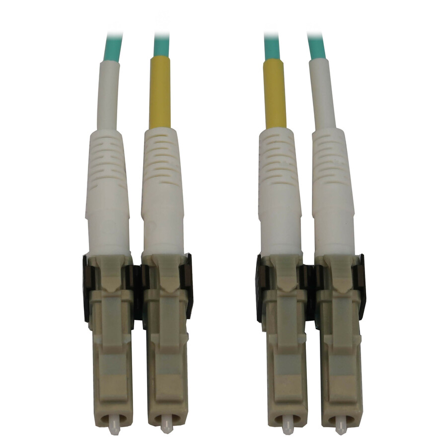
Passive DAC is efficient for the first few meters inside a rack or between adjacent equipment. Multimode fiber is common across rows and rooms. Single-mode fiber becomes the durable choice where reach, pathway reuse, or future optic changes justify it. The active interface and fiber plant must be matched: wavelength, connector, polarity, lane count, and optic standard all matter.
Pathway and lifecycle
Fiber can carry more bandwidth over a smaller, lighter pathway, but it requires suitable termination, inspection, cleaning, and test equipment. Copper can carry power to endpoints; fiber cannot. The right design often uses fiber for the backbone and copper for final PoE access-point, camera, or phone drops.
OM3, OM4, and OS2 are not interchangeable labels
OM3 and OM4 are laser-optimized multimode fiber grades. For 10GBASE-SR, the existing standards table uses 300 meters for OM3 and 400 meters for OM4. For parallel higher-speed Ethernet variants, the allowable distances change with the specific physical-layer standard. Do not copy the 10GbE number into a 40GbE or 100GbE design.
OS2 is single-mode fiber. Standardized LR interfaces commonly target kilometer-scale reach, including 10 km for the 10G, 25G, 40G, and 100G LR variants represented in the existing tool. A long-reach optic is not automatically suitable for a very short direct connection; receiver limits and vendor guidance still apply.
The word "fiber" is therefore not enough for a bill of materials. Record:
Fiber grade and strand count.
Connector type and polish.
Duplex or parallel lane design.
Transceiver Ethernet application.
Wavelength and reach class.
Polarity method.
Patch-panel and cassette path.
End-to-end loss budget and test method.
DAC and AOC length decisions
Direct-attach copper combines the cable and transceiver ends into a matched assembly. It avoids separate optics and usually offers attractive cost and power for short links. Passive DAC reach is limited; the exact ceiling changes by speed and specification. The live table preserves those speed-specific values rather than presenting one universal DAC limit.
Active optical cable also integrates the optical engines and cable. Unlike a standardized pluggable optic plus structured fiber link, AOC length is a vendor product attribute. The existing tool labels its 1–30 meter range as typical and does not use it as a hard standards pass mark. Keep that caveat.
Before ordering DAC or AOC, verify switch and NIC compatibility, supported coding, form factor, breakout behavior, and whether the assembly is directional. A connector that physically fits does not prove the port firmware accepts that part.
PoE does not extend or shorten the data-channel standard
Power over Ethernet operates across the same structured-cabling channel. The familiar 100-meter maximum still applies. Power introduces additional design work: voltage drop, conductor resistance, bundle heating, ambient temperature, cable gauge, connector condition, and the difference between power sourced at the switch and power guaranteed at the endpoint.
For high-power endpoints, choose the cable and bundle design against the applicable TIA power-delivery guidance and local code. Do not reduce the problem to "Cat6a is always required" or "PoE works on any 100-meter cable." The endpoint load, cable construction, bundle, environment, and installation method decide the thermal margin.
How to measure and specify a run
1. Start with the application
Name the Ethernet physical layer: 1000BASE-T, 10GBASE-T, 10GBASE-SR, or another exact application. "Fast Ethernet" and "fiber uplink" are not testable requirements.
2. Measure the routed distance
Follow the actual tray, conduit, riser, and rack path. Include vertical travel and sensible service loops. Keep permanent-link length separate from patch cords.
3. Record the environment
Note indoor or outdoor use, plenum or riser requirements, temperature, moisture, sunlight, chemical exposure, crush risk, and electrical noise. Jacket and listing requirements are safety and durability decisions, not speed upgrades.
4. Choose copper, DAC/AOC, multimode, or single-mode
Use the live picker to narrow products only after speed and distance are known. If a route is at a boundary, prefer design margin over a laboratory maximum.
5. Define termination and testing
Specify connectors, panels, patch cords, and certification method. For installed copper, request application-compliant certification results. For fiber, capture loss and polarity evidence appropriate to the link.
6. Save the result with the asset record
The useful handoff includes cable ID, endpoints, route, length, category or fiber grade, test record, and switch-port application. That record speeds future moves and prevents an unknown legacy run from being treated as a guaranteed 10GbE path.
Buyer checklist
Name the required Ethernet speed and physical layer.
Measure the full routed path rather than straight-line distance.
Reserve channel allowance for patch cords and service loops.
For 10GbE beyond 37 m on existing Cat6, require assessment; use Cat6a for dependable new full-channel deployment.
Use fiber when distance, electrical separation, noise, or backbone lifecycle demands it.
Match fiber grade, optic standard, wavelength, connector, and polarity.
Verify exact DAC or AOC support against both ports.
Plan PoE thermal and voltage-drop conditions separately from data reach.
Specify the field test and acceptance result.
Keep the test record with the cable and port inventory.
What a useful cable handoff contains
An installation is not complete when the link light turns green. The owner should receive a cable schedule that identifies both endpoints, cable ID, route, permanent-link length, category or fiber grade, termination hardware, and the application for which it was tested. Copper records should include the field tester, calibration status, test limit, and pass result. Fiber records should identify the launch/reference method, measured loss, length, polarity, and any inspected or remediated connector.
Keep that evidence tied to the switch-port and room inventory. When a later upgrade proposes 10GbE, PoE, or a new optical interface, the engineer can evaluate a known channel instead of guessing from jacket color. A failed result should retain the original measurement and the remediation record; overwriting it removes the history that explains why a pathway or termination was changed.
For patch cords and integrated assemblies, preserve the exact manufacturer part number and length. DAC and AOC substitutions deserve a compatibility check at both attached ports. A seemingly harmless replacement can change supported coding, breakout behavior, reach, or vendor support even though the connectors look the same.
Assign ownership for remediation before installation begins. If a permanent link fails certification, the record should identify who diagnoses, repairs, retests, and accepts it so the switch migration does not stall after equipment arrives.
Audit an existing route before reuse
Start at both labeled endpoints and trace the pathway rather than trusting an old spreadsheet. Record every patch panel, coupler, consolidation point, wall jack, and patch cord. Compare the routed length with the application limit, then inspect bend radius, strain, crushed sections, unsupported cable, moisture exposure, and proximity to electrical equipment. Jacket printing can help identify construction and category, but it does not prove that terminations or the full channel pass.
Use the appropriate field instrument and test limit for the intended Ethernet application. Save the original result, remediation, and retest instead of keeping only a final “pass.” For fiber, inspect and clean connectors before measuring loss; for copper, resolve split pairs, excessive loss, return loss, and crosstalk findings using the installer's diagnostic process.
If the route cannot be verified, classify it as unknown rather than as reusable Cat6 or fiber. That status gives the project an honest choice: qualify it, replace it, lower the planned speed, or move to another medium.
Related
FAQ
Cable length questions
- What is the maximum length of an Ethernet cable?
- For common twisted-pair Ethernet applications, the maximum is a 100-meter channel, or 328 feet, including patching. Plan the permanent horizontal link to 90 meters so patch cords remain within the channel budget. Other media and speeds have different standardized reaches.
- What is the Cat6 maximum length at 10GbE?
- The existing tool follows TIA TSB-155-A guidance: 37 meters in the worst alien-crosstalk case and up to 55 meters after mitigation and assessment. For a new longer 10GBASE-T run, Cat6a supports the full 100-meter channel and is the safer specification.
- Does Cat6a extend 1GbE beyond 100 meters?
- No. Cat6a gives additional transmission headroom and supports 10GBASE-T across the full standard channel, but ordinary BASE-T channel length remains 100 meters. Use an intermediate switch or fiber for a longer route.
- Is OM4 always better than OM3?
- OM4 provides additional multimode reach for several applications, but the benefit depends on the exact transceiver standard. If OM3 already meets the distance with margin, changing fiber grade alone does not increase the port's negotiated speed.
- Does PoE change Ethernet's distance limit?
- No. The data-channel limit remains. PoE adds voltage-drop and heating considerations, so the source must have enough budget for the endpoint and the cable installation must be suitable for the load and environment.
Need help sizing it?
Send the run lengths, the switch ports at each end and the count — we come back with media, connectors and a total, screened for NDAA §889 status before checkout, with TAA verified on request.