
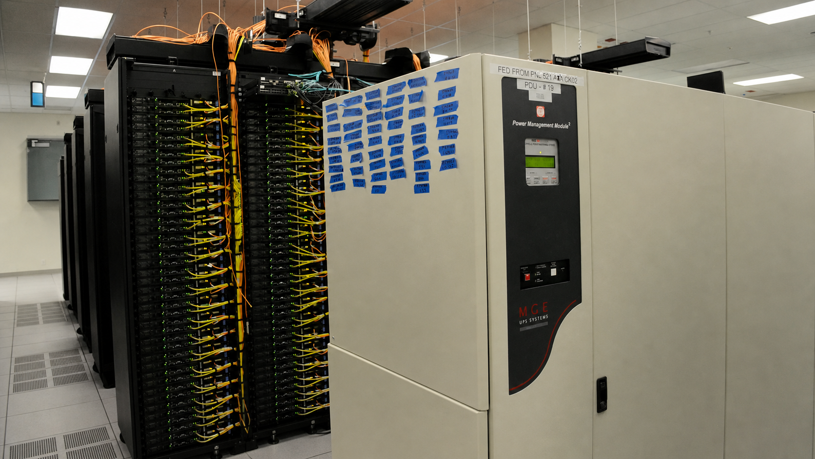
Short answer
A UPS (uninterruptible power supply) holds equipment up on stored energy when utility power fails or drifts outside acceptable limits — long enough to ride through a dip, bridge to a generator, or shut down cleanly. Three topologies exist: standby, line-interactive, and online double conversion, which feeds the load from its inverter continuously.
Key facts
- IEC 62040-3:2021 specifies the performance and test requirements for uninterruptible power systems. Edition 3.0 was published on 21 April 2021.
- Online double conversion rectifies incoming AC to DC and inverts it back continuously, so the load is always fed from the inverter rather than the mains.
- Runtime depends on the unit, battery configuration, load, battery condition and temperature — use the manufacturer's runtime curve, not a rule of thumb.
- Output waveform is a datasheet line: pure sine wave, or a stepped and pulse-width-modulated approximation of one.
- APC advises sine wave output for sensitive electronics and names screen flicker, computer crashes and sound interference as what it avoids.
- A maintenance bypass switch routes the load to utility power so the UPS can be serviced or swapped without dropping the equipment behind it.
By Uniqcli Team
A UPS, or uninterruptible power supply, keeps an approved load powered when utility input fails or moves outside the UPS operating window. Its stored energy can bridge a brief outage, carry equipment until a generator stabilizes, or provide time for an orderly shutdown. Correct sizing requires the load’s watts and VA, the required minutes, the exact model’s runtime data, and a plan for batteries, monitoring, installation, and failure states.
What a UPS actually does
UL Solutions describes a UPS as equipment that provides emergency power when the main source fails, normally using stored energy such as batteries. The key behavior is speed: the UPS can continue supplying the connected load without waiting for an engine generator to start.
That continuity supports three common outcomes:
- Ride through: the utility disturbance ends before usable battery runtime is exhausted.
- Bridge: the UPS carries the load until a generator or alternate source is stable and accepted.
- Shut down: management software closes applications and powers systems off before the battery reaches its cutoff.
A UPS can also respond to power conditions other than a complete outage. The scope depends on topology and model. Possible functions include surge protection, voltage regulation, frequency regulation, noise filtering, and output-waveform control. Do not infer all of them from the word UPS; verify the data sheet and IEC performance classification.
The connected equipment still needs other resilience. A UPS does not repair a failed server power supply, create application redundancy, protect an unconnected network path, or guarantee that a generator will start. It is one layer in the electrical and service design.
The main components
Most static UPS designs combine a rectifier or charger, energy storage, an inverter, control electronics, and a transfer or bypass path appropriate to the topology.
Rectifier or charger. It converts incoming power as needed to maintain the DC bus and charge the batteries. Charging behavior and recharge time depend on the system and battery configuration.
Energy storage. Batteries are common, though UL notes that other stored-energy forms exist. Battery chemistry, number of strings, voltage, cabinet, monitoring, and replacement rules are part of the certified system — not interchangeable accessories.
Inverter. It converts DC energy into AC output for the load. In an online double-conversion design it normally carries the load continuously; in other designs it becomes the source during battery operation.
Transfer and bypass paths. A standby or line-interactive unit transfers the load to its inverter when input is unacceptable. Many online systems also include static and maintenance-bypass arrangements. Those paths have ratings, conditions, and operational procedures that must be understood before service.
Controls and communications. Local displays, USB or serial links, relay contacts, and network cards expose load, battery, input, output, alarms, and shutdown functions. The available metrics and licenses vary by product.
Three UPS topology families
IEC 62040-3 classifies UPS performance by input dependency. Industry explanations commonly map the families this way: VFD to standby/offline, VI to line-interactive, and VFI to online double-conversion. The IEC code and exact tested behavior are more precise than a marketing label, so retain the current model documentation.
Standby or offline
The load normally receives utility power. When input leaves the allowed window, the UPS transfers to its inverter and battery. This is a simple approach for supported, less-critical loads. It has a nonzero transfer interval and typically less continuous conditioning than the other families.
Line-interactive
The load normally follows the utility path, while automatic voltage regulation can correct certain input-voltage variation without consuming the battery. The UPS transfers to battery and inverter when needed. This topology often fits network closets, edge systems, and general IT where the site is reasonably stable and the equipment can tolerate the documented transfer.
Online double-conversion
The normal path converts incoming AC to DC and then back to AC through the inverter. The inverter already supplies the load, so a normal loss of utility does not require the output to transfer from utility to inverter. This provides voltage- and frequency-independent behavior within the system’s design.
Online does not mean that every possible event has zero transfer. A move to or from bypass, overload response, internal fault, eco mode, or maintenance operation can behave differently. Review the single-line diagram, operating modes, bypass conditions, and transfer specifications for the exact model.
UPS, surge protector, and generator are different
A surge protective device diverts or limits transient surge energy. It does not supply battery power during an outage. A UPS provides stored-energy continuity and may also include surge protection and other conditioning, but a point-of-use UPS does not replace a coordinated facility surge-protection design.
A generator supplies longer-duration power as long as fuel and supporting systems remain available. It takes time to detect failure, start, stabilize, and accept load. The UPS bridges that interval. Generator and UPS compatibility still requires engineering: voltage and frequency behavior, waveform distortion, load steps, neutral and grounding, charger input, and generator capacity can affect whether the UPS accepts the source.
Do not improvise the connection order. A UPS manufacturer may require the UPS to connect directly to a correctly wired branch receptacle and prohibit surge strips or extension cords on its input or output. Follow the listing, label, installation manual, electrical design, and local code.
Size both watts and VA
Watts represent real power consumed by the load. Volt-amperes represent apparent power. The UPS has limits for both. A candidate must satisfy both limits under normal, startup, and supported transient conditions.
Build a load table using measured power where feasible and current manufacturer planning data for new equipment:
| Load | Normal W | Planning/peak W | VA or power factor | Inrush or special behavior | Shutdown priority |
|---|---|---|---|---|---|
| Server or storage | measured | vendor model/measurement | documented | PSU and workload dependent | ordered |
| Network equipment | measured | include enabled PoE load | documented | PoE startup can matter | critical |
| Firewall/router | measured | documented maximum mode | documented | redundant inputs if used | critical |
| Management device | measured | measured | documented | must outlive managed loads | last |
For a planning total:
- UPS planning watts = sum of simultaneous protected-load planning watts
- UPS planning VA = sum of simultaneous protected-load VA
If only watts and a documented load power factor are known, apparent power can be estimated as:
- VA = watts ÷ power factor
Do not substitute the UPS output power factor for the load’s power factor. Do not add the two power supplies of a redundant server as though each always draws the full server load; model the actual sharing and the failure state in which one source carries the equipment.
Leave capacity for defined growth and transient behavior, but avoid a universal headroom percentage. Excessive oversizing can move a UPS into a less efficient operating region and raise capital and battery cost. ENERGY STAR evaluates UPS efficiency at multiple load points because efficiency changes with loading.
Runtime is not a straight-line calculation
Runtime depends on load, battery configuration, chemistry, age, temperature, charge state, inverter losses, cutoff behavior, and the manufacturer’s controls. Doubling load does not reliably halve runtime, and a battery’s nameplate watt-hours do not produce a safe installed runtime promise.
Use this process:
- Define the event: brief ride-through, generator bridge, or shutdown.
- Measure or estimate the simultaneous load after any planned shedding.
- Select an exact UPS and battery configuration that passes both watts and VA.
- Read the manufacturer’s runtime curve or selector at that load.
- Confirm whether the data reflects new batteries, ambient assumptions, output mode, and external battery modules.
- Apply the organization’s aging and contingency policy.
- Test the deployed system under a controlled load and record the result.
If shutdown takes eight minutes after the alert and operations require a buffer, the required runtime is not simply eight minutes. Include detection, management communication, application quiescing, virtual-machine order, storage protection, operating-system shutdown, and uncertainty. Define the buffer through a risk review rather than copying a generic number.
For generator-backed sites, time the complete sequence under a supervised test: loss of source, generator start, stabilization, transfer, and UPS acceptance. A generator may be running while the UPS continues on battery because input remains outside the accepted window.
Decide what stays on battery
Protecting every plug can reduce runtime and hide the truly critical path. Map dependencies. A server may need storage, directory services, DNS, switching, firewall, WAN equipment, and the UPS management network to complete an orderly shutdown. A network switch with PoE may be carrying phones, cameras, access points, and sensors whose aggregate draw changes by configuration.
Separate outlets or load groups where the UPS supports them. Lower-priority equipment can shut down first so essential management and network functions retain energy. Document which outlet is battery-backed and which, if any, is surge-only. Labels should match the management configuration.
Keep printers, heaters, vacuums, motors, and other high-inrush or unsupported loads off the battery output unless the manufacturer explicitly approves the equipment and the system is engineered for it. A laser printer can create a load step that a small UPS was never intended to supply.
Redundancy changes the calculation
Dual-corded IT equipment often connects to independent A and B power paths. In normal operation the load may share between them; after one path fails, the survivor must carry the required load. Size and test each path for its failure responsibility.
Avoid creating two labels on one dependency. Two UPS outputs fed from the same branch circuit, sharing one bypass, or using the same battery cabinet may not provide the intended independence. Trace utility, switchgear, generator, transfer, UPS, PDU, rack distribution, and equipment power supplies.
Single-corded equipment may use an approved transfer device where the design calls for one. Verify transfer behavior with the load and UPS topology. Redundancy architecture should be reviewed by qualified electrical and infrastructure professionals, not inferred from cord count.
Outlets, input, and physical fit
Confirm input voltage, phase, frequency, plug or hardwire requirement, branch circuit, overcurrent protection, receptacle, and installation instructions. A larger UPS may require a different circuit or professional installation. Never solve a mismatch with an unapproved adapter.
On the output side, count usable receptacles after plug size and cable routing. Match connector types and ratings. For rack systems, check rack units, chassis and rail depth, weight, front/rear clearance, battery-module placement, PDU interference, airflow, and service access. Floor and rack loading need review because battery systems are heavy.
Heat matters. The UPS and batteries add thermal load to the room, and efficiency changes by model and operating point. Use the vendor’s heat-rejection data for the selected configuration and mode, not a category average.
Battery planning
Batteries are consumables. Life varies with chemistry, ambient and internal temperature, number and depth of discharges, charging, storage, cell quality, and UPS design. Calendar age alone is not a complete health measure; a status light alone is not proof of runtime.
Create a record with UPS serial, battery type and approved replacement identifier, installation date, ambient trend, self-test results, alarms, measured load, runtime-test result, warranty, and disposal route. Follow the manufacturer’s procedure for inspection and testing. Swelling, leakage, odor, excessive heat, damage, or repeated faults require safe escalation.
Use only approved battery assemblies and instructions. UL explains that replacement markings and documentation are part of UPS safety certification. A pack that fits electrically may not preserve the listing, charging behavior, thermal protection, or support.
Plan the maintenance window before the alarm appears. Determine whether replacement is hot-swappable, what risk exists during service, whether an external bypass is present, and who is qualified to perform the work. Recycle batteries through an authorized route.
Management and graceful shutdown
A UPS without a tested response can delay an abrupt failure rather than prevent one. Define alarm thresholds and shutdown order. The management device, network path, hypervisor, storage, and applications must remain reachable long enough to execute the plan.
Test authentication, certificates, time sync, notification, role access, monitoring, and shutdown agents. Protect management interfaces from unnecessary exposure and keep firmware under change control. Record what happens when the management network is unavailable.
Run a supervised outage test using a safe method approved by facilities and the manufacturer. Confirm alerts, load shedding, application shutdown, UPS cutoff, restart policy, and recovery when power returns. A shutdown script that has never been exercised is not runtime assurance.
Acceptance checklist
- Define protected services, dependencies, event purpose, and required minutes.
- Measure load and record both planning watts and VA.
- Model redundant-power failure states and enabled PoE loads.
- Select topology from power quality and load tolerance.
- Check exact-model runtime data at the planned load and battery configuration.
- Verify input circuit, voltage, phase, plugs, outlets, waveform, and supported load types.
- Confirm rack, floor, airflow, heat, noise, and service constraints.
- Price network management, shutdown software, licenses, batteries, bypass, and installation.
- Document generator interaction where applicable.
- Establish battery inspection, testing, replacement, and recycling.
- Test alarms, shutdown, bypass, recovery, and failure behavior.
- Store the as-built diagram and acceptance result with the asset.
Establish the operating baseline
After acceptance, capture a baseline while batteries are known to be healthy and the protected service is working normally. Record input and output voltage, load watts and VA, power factor where exposed, battery charge and temperature, estimated runtime, operating mode, alarm state, firmware, and ambient conditions. Keep the model's runtime curve and the approved load inventory beside that record.
Trend the measurements rather than treating one display value as permanent. A rising load can reflect a new server, enabled PoE devices, or changed power sharing. Falling runtime can reflect battery aging, temperature, calibration, or load growth. An increase in transfers may point to a changing utility or generator input rather than a battery defect.
Define alert owners and escalation. A low-runtime warning, failed self-test, unavailable bypass, lost network card, overloaded outlet group, or high temperature should lead to a named action and time. Review the baseline after configuration, battery, firmware, circuit, or generator changes so the shutdown plan remains tied to the system that is actually installed.
Common mistakes
Sizing only by VA. The watt rating may be reached first. Check both.
Adding power-supply nameplates as actual load. Use measurement and configuration-aware planning while preserving appropriate worst-case checks.
Treating runtime as linear. Use the exact model’s curve and validate the deployed system.
Buying online because it sounds superior. Continuous conversion has benefits and tradeoffs; match it to a documented requirement.
Leaving dependencies off battery. A server cannot shut down cleanly if its storage or management network disappears first.
Ignoring maintenance. Batteries, fans, filters where present, firmware, and bypass procedures require ownership.
Key takeaways
- A UPS supplies near-instant backup power; it is usually a bridge or shutdown resource, not a substitute for long-duration generation.
- Size against both the UPS watt limit and VA limit, then check outlets, voltage, input circuit, inrush, supported load type, and growth.
- Runtime is load-dependent and nonlinear. Use the manufacturer’s curve or selector for the exact UPS, battery age assumption, and external-battery configuration.
- Standby, line-interactive, and online double-conversion topologies address different power conditions. Buy the topology the load and site require.
- A network management card and tested shutdown sequence can be more valuable than extra unattended minutes.
- Batteries are maintained components. Temperature, age, cycling, model compatibility, inspection, testing, and approved replacement all matter.
Shop it at Uniqcli
Parts for this job
Standby, desk
Eaton
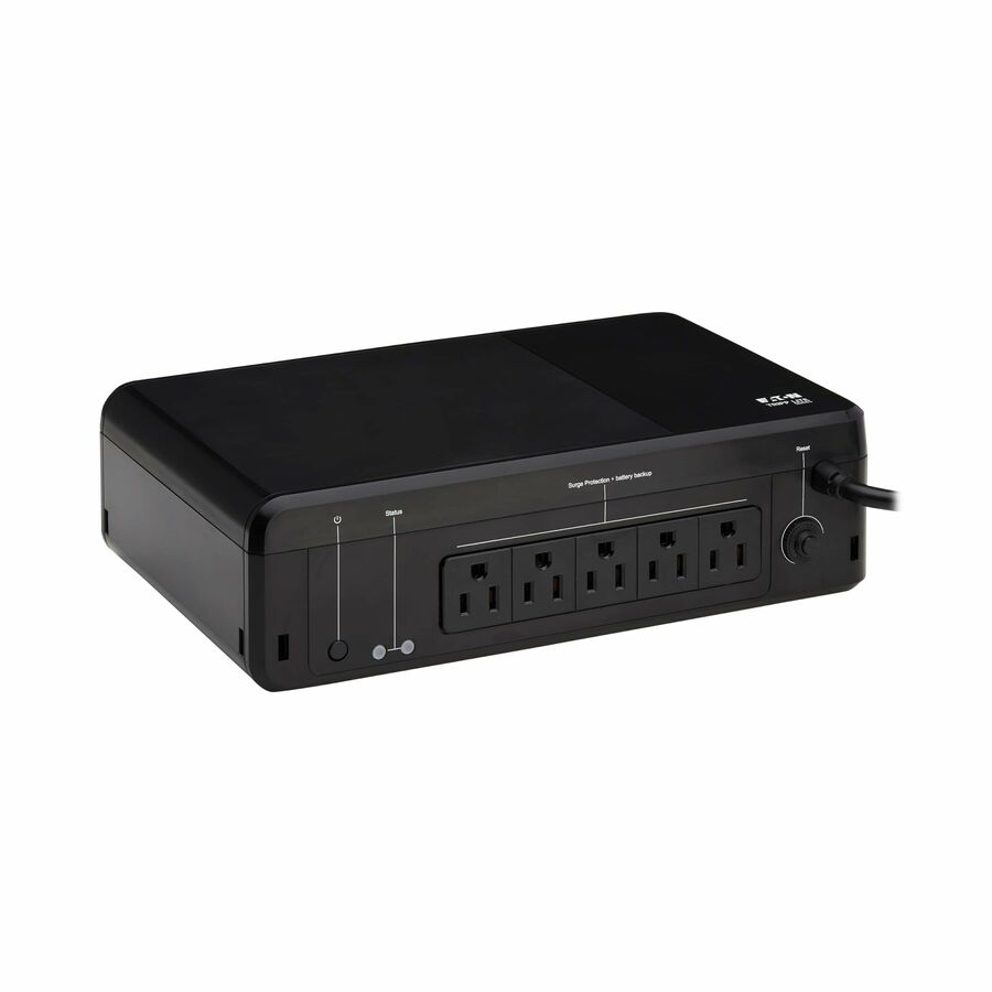
Eaton Tripp Lite Series 600VA 300W 120V Standby UPS
BC600R
A 600 VA / 300 W standby UPS with four battery-backed NEMA 5-15R outlets, desktop or wall mount. The tier for a single workstation or a small appliance.
This model's listing gives its output as a pulse-width-modulated sine wave; step up to the online unit where the load is waveform-sensitive.
$146.28Back-orderedLine-interactive with AVR
Eaton
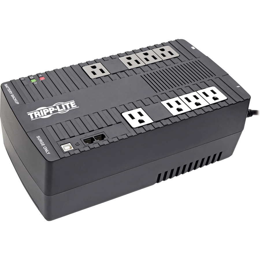
Tripp Lite by Eaton UPS 550VA 300W Line-Interactive UPS
AVR550U
A 550 VA / 300 W line-interactive unit with automatic voltage regulation across eight outlets, four of them battery-backed, and USB monitoring.
AVR corrects sags and swells without discharging the battery, which is what makes line-interactive worth the step up on a poor feed. Its listing also gives a pulse-width-modulated sine wave output; the online unit is the waveform-sensitive answer.
$149.96In stockOnline double conversion
Vertiv
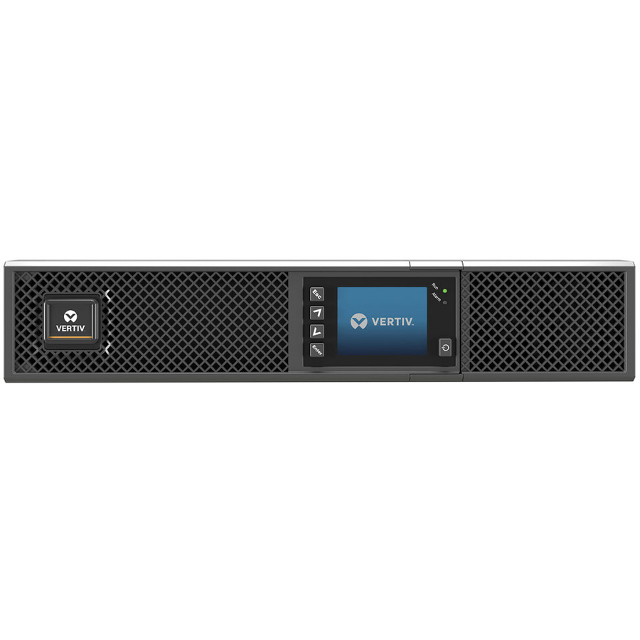
Vertiv Liebert GXT5 UPS
GXT5-1000LVRT2UXL
A 1000 VA / 1000 W online double-conversion UPS in a 2U rack or tower body with a graphic LCD and an option slot for a network card. The rack-room tier.
$1,467.35In stockFrequently asked
- What is a pure sine wave UPS?
- One whose inverter reproduces the utility waveform on battery rather than a stepped approximation of it. The output waveform is a line on the datasheet. APC describes stepped-approximated power as the rougher version most basic battery backups generate, advises sine wave output for sensitive electronics, and says sine wave output avoids screen flicker, computer crashes and sound interference. Online double-conversion units produce a sine wave by construction, because the load always runs off the inverter.
- What is a UPS maintenance bypass switch?
- A switch that routes the load straight to utility power so the UPS can be serviced, have its batteries replaced or be swapped out without dropping the equipment behind it. Without one, any UPS work is an outage. It is specified with the UPS, not added later, because it has to match the input and output arrangement.
- What does UPS stand for?
- UPS stands for uninterruptible power supply. It uses stored energy to maintain output when the normal source fails or becomes unacceptable, allowing ride-through, generator bridging, or an orderly shutdown.
- How do I calculate UPS size?
- Total the simultaneous protected load in watts and VA, including failure states, inrush, PoE, and defined growth. Choose a unit that passes both ratings, then use its exact runtime data at that load. Also verify voltage, outlets, circuit, topology, and supported load types.
- How long will a UPS run?
- Runtime varies by exact UPS, battery configuration, load, battery condition, temperature, and operating mode. Use the manufacturer’s curve or selector for the specific configuration, then validate the installed system. Do not scale runtime linearly from a single published point.
- Is a UPS the same as a battery backup?
- Battery backup describes the continuity function, but a UPS may also provide monitoring, surge protection, voltage regulation, or continuous power conversion. The exact feature set depends on topology and model.
- Can a UPS replace a generator?
- Usually not for a long outage. A UPS provides immediate, limited-duration energy; a generator can support longer operation once it starts and stabilizes. Resilient sites often use both and test their interaction.
Sources
Keep reading