
Short answer
Power over Ethernet sends DC power and Ethernet data over the same copper cabling to a compatible endpoint. Three IEEE generations define it — 802.3af, 802.3at and 802.3bt — and each link has to satisfy two limits at once: the port must deliver the endpoint's class, and the switch's total power budget must cover every active device at the same time.
Key facts
- Every PoE link has two numbers: what the port sources and what reaches the device after channel loss. Compare an endpoint against the device-side figure.
- IEEE 802.3af (Type 1) tops out at class 3: 15.4 W at the port, 12.95 W at the device. 802.3at (Type 2) adds class 4 at 30 W and 25.5 W.
- IEEE 802.3bt adds classes 5 to 8 using all four pairs and provides up to 71.3 W at the powered device.
- PoE does not shorten the 100 m Ethernet channel. Higher power raises the weight of conductor resistance, bundle heating and ambient temperature within it.
- Per-port capability and the switch's aggregate budget are separate specifications: 48 PoE-capable ports rarely means 48 endpoints at each port's maximum.
- Standards-based PoE detects and classifies an endpoint before energizing the pairs. Proprietary passive-power products do neither and are not interchangeable.
By Uniqcli Team
Power over Ethernet, or PoE, sends DC power and Ethernet data over the same balanced copper cabling to a compatible endpoint. It can eliminate a local outlet for an access point, camera, phone, sensor, or other networked device. PoE wattage has to satisfy two limits at once: each port must deliver the endpoint's required class, and the switch must have enough total power budget to serve all active devices under the intended operating condition.
PoE components: PSE, PD, and the channel
PoE has three parts. The power sourcing equipment, or PSE, is usually a network switch or midspan injector. The powered device, or PD, is the access point, camera, phone, or other endpoint. Between them is a standards-compliant Ethernet channel consisting of fixed cable, connectors, and patch cords.
The PSE does not blindly energize every connected cable. Standards-based PoE uses detection and classification behavior so the source can identify a compatible powered device and determine a power allocation. That design supports backward compatibility across the IEEE PoE generations. Proprietary passive-power systems are different and should never be treated as interchangeable with standards-based PoE merely because they use an Ethernet connector.
The endpoint's data rate and power class are related through one cable but remain separate capabilities. A device can use a relatively modest Ethernet data rate while drawing substantial power, or demand multigig data while drawing little. Confirm both sides.
PoE wattage: source power versus device power
The maximum number printed beside a PoE standard often describes power from the PSE. The power guaranteed to the PD is lower because the standard allows for cable loss.
| Type | Common shorthand | Pairs used for power | Maximum at PSE | Maximum available at PD |
|---|---|---|---|---|
| Type 1, IEEE 802.3af | PoE | 2 | 15.4W | 12.95W |
| Type 2, IEEE 802.3at | PoE+ | 2 | 30W | 25.5W |
| Type 3, IEEE 802.3bt | Four-pair PoE | up to 4 | 60W | 51W |
| Type 4, IEEE 802.3bt | Higher-power four-pair PoE | 4 | 90W | 71.3W |
These standard figures are not a forecast of actual draw. A standards-compliant endpoint negotiates or advertises a class and consumes according to its design and active features. A 90W-capable switch port does not force 90W into a smaller device.
For procurement, use the PD-side requirement from the exact endpoint data sheet. Compare it with the switch's supported type and class. Do not compare an endpoint's input need with only the larger PSE-side marketing number.
Types, classes, and marketing names
IEEE PoE classes give the source a bounded allocation and the device a defined available-power range. Type 1 covers Classes 0–3, Type 2 uses Class 4, Type 3 adds Classes 5–6, and Type 4 adds Classes 7–8. The exact allocation behavior and options are more detailed than the common four-row summary, which is why a specification should name the IEEE type and required device class where possible.
"PoE+" normally refers to IEEE 802.3at. "PoE++" is used inconsistently in product marketing for higher-power operation. Vendors also have proprietary brand names for power features. Those names can describe useful capabilities, but they are not substitutes for proof that a PSE and PD interoperate at the required IEEE class.
Ask for:
- IEEE PoE type and supported classes on the switch port.
- Required class and maximum input at the endpoint.
- Number of pairs used for the required mode.
- Whether full endpoint functions require a higher class than basic operation.
- Whether power negotiation relies on physical classification, LLDP, vendor extensions, or a combination.
- The switch's aggregate budget under the installed power-supply configuration.
Why endpoints can work but lose features
Many devices can boot on a lower power allocation and disable some functions. A wireless access point may reduce radio chains, USB output, or other features. A camera may restrict heaters, illuminators, motors, or auxiliary output. A display or thin client may reduce brightness or peripheral power.
That partial operation is dangerous in acceptance testing. A link light and a reachable management page do not prove the device received the planned budget. Commission the exact operational mode: radios active, camera heater on, pan/tilt/zoom moving, downstream USB loaded, or other peak feature enabled.
Record both the negotiated class and the device's observed operational state. If the switch reports a lower allocation than expected, investigate the cable, endpoint configuration, PSE capability, and negotiation method before declaring success.
Per-port capability is not total switch capacity
Suppose a 48-port switch supports a 30W class on every port. Multiplying 48 by 30W gives 1,440W, but the switch may have an aggregate PoE budget well below that. Port capability says what one port can negotiate. Aggregate budget says how much all ports can consume at once.
Build the budget from endpoints rather than port count:
| Endpoint group | Quantity | Planned PD demand | Subtotal |
|---|---|---|---|
| Wireless access points | 24 | use exact model maximum | quantity × demand |
| Cameras | 18 | include heater/IR/PTZ mode | quantity × demand |
| Phones | 30 | include expansion modules | quantity × demand |
| Sensors or controllers | 12 | use exact input rating | quantity × demand |
| Growth allocation | planned | documented policy | added separately |
Do not fill the worksheet with the class ceiling for every device unless that is the only reliable evidence. Manufacturer maximum consumption is often more useful for capacity planning, provided it includes all enabled options. Conversely, do not size from a short idle measurement. The design must survive the supported maximum operating condition.
Then compare the total with the switch's available budget in the actual hardware configuration. Some switches change PoE capacity when a larger power supply, second power supply, or redundant mode is installed. A pair of supplies might operate as combined capacity or reserve one supply for redundancy. Read the platform's power-supply and PoE rules rather than assuming watts add together.
Headroom and redundancy
Headroom is not one universal percentage. It should cover named uncertainties:
- Devices that draw more when radios, motors, heaters, lighting, or USB ports activate.
- Future endpoint additions already included in the site plan.
- Model substitutions with a higher documented requirement.
- Loss of one power supply or one switch in a resilient design.
- Environmental derating documented by the manufacturer.
- Startup behavior and simultaneous restoration after an outage.
Write the policy. For example: "The access switch must support the installed load plus the next four planned APs while one power supply is unavailable." That statement is testable. "Add 20 percent" is only a placeholder until it is tied to an operating condition.
When switches are stacked or paired, decide whether endpoints remain powered during member failure. Data-path redundancy does not automatically preserve power. A camera connected to one switch loses power with that switch unless the endpoint has a second power path or the design provides another recovery mechanism.
Cable loss, temperature, and bundle heating
The difference between PSE and PD wattage accounts for allowable channel loss. Real loss is affected by conductor resistance, channel length, connector quality, temperature, and current balance. Higher-power four-pair PoE increases the importance of cable and installation design.
Large bundles can retain heat. Higher temperature raises conductor resistance, which increases loss. Smaller-gauge patch cords and high connector resistance can further reduce margin. The answer is not to invent a shorter Ethernet limit. The standards channel remains 100 meters. Instead, use cabling and installation guidance appropriate to the power level, bundle, ambient environment, and local requirements.
The cabling plan should specify:
- Recognized category and conductor construction.
- Permanent-link and patch-cord lengths.
- Patch-cord gauge where relevant to the power design.
- Bundle size and pathway ventilation.
- Ambient temperature and environmental rating.
- Connector and patch-panel rating.
- Field test and visual-inspection requirements.
- Separation and code requirements for the installation.
Avoid copper-clad aluminum and undocumented assemblies. For critical or high-power links, buy traceable components from known manufacturers and retain the cable data sheet with the project record.
PoE and Ethernet distance
PoE does not grant extra distance and does not create a different Ethernet data-channel maximum. The same 100-meter structured-cabling channel applies to the common BASE-T applications discussed here. Extenders and repeaters are active devices that create additional segments; they are not a way to redefine one channel.
If an endpoint lies beyond the copper channel, consider fiber to a local switch with suitable power, a properly engineered media-and-power enclosure, or another supported architecture. Do not hide an active extender above a ceiling without documenting its power, environment, management, and failure behavior.
Midspan injectors and splitters
A standards-based midspan injector can add PoE between a non-PoE switch and a compatible endpoint. It still has a supported IEEE type, class, data rate, environmental range, and input-power requirement. Confirm that it passes the required Ethernet speed; an old injector can become a data bottleneck in a multigig deployment.
A splitter converts PoE at the far end to another voltage or connector for a non-PoE device. That adds efficiency loss and another compatibility point. Record the splitter's PoE input class, DC output, connector polarity, output limit, and environmental rating. The combination is not automatically supported by the endpoint manufacturer.
For multiple devices, a managed PoE switch generally provides better telemetry, remote reset, scheduling, and fault visibility than a collection of injectors. Injectors remain practical for one-off additions or specialized locations.
Managed power features
A managed switch can expose per-port allocation, actual draw, class, faults, and administrative state. It may support scheduled power cycling or API-driven recovery. These capabilities improve operations but do not increase the physical budget.
Use telemetry to refine the deployment after it is safely sized:
- Alert when total draw approaches the defined operating threshold.
- Track repeated endpoint power resets.
- Compare normal and seasonal device demand.
- Identify ports whose negotiated class does not match the design.
- Preserve power-priority settings for controlled shedding during a constrained condition.
Power priority is especially important where the switch cannot support every configured port after a supply failure. Rank emergency phones, security cameras, access control, and network infrastructure deliberately. Do not accept a default port-order policy without review.
A practical PoE planning workflow
1. Inventory endpoints by exact model
Count current devices and planned growth. Capture optional modules and environmental features.
2. Record PD-side requirements
Use the vendor's maximum input and required IEEE type/class. Note reduced-function modes.
3. Validate the channel
Check category, length, pathway, bundle, temperature, connectors, and field results.
4. Select ports and switch architecture
Confirm per-port class, multigig data need, uplinks, and management features.
5. Calculate aggregate demand
Add endpoint maxima by group. Add named growth and resilience requirements.
6. Validate the power-supply mode
Determine the budget with the actual supplies and redundancy configuration.
7. Commission at peak function
Exercise radios, heaters, motors, lighting, and downstream power. Verify negotiation and switch telemetry.
8. Save evidence
Keep endpoint data sheets, switch power tables, cable records, configuration export, and acceptance results.
Buyer checklist
- Exact PD model, firmware, and optional features.
- PD-side maximum wattage and required IEEE class.
- PSE per-port type/classes and supported data rate.
- Aggregate PoE budget in normal and failure modes.
- Power-supply quantity, capacity, and redundancy policy.
- Current endpoint count plus documented growth.
- Cable type, gauge, channel length, bundle, and temperature.
- Priority and load-shedding order.
- Peak-function commissioning method.
- Monitoring, alerting, and remote-reset requirements.
Acceptance criteria for a PoE site
Write acceptance criteria before devices arrive. Each endpoint should negotiate the planned class, expose its full intended feature set, and remain stable during a peak-function test. The switch should stay below the documented budget threshold in normal service and in the agreed power-supply failure mode. Cabling results and port labels should match the device inventory.
Test restoration after a controlled outage. A design can appear healthy during steady state but exceed the available budget when many endpoints start together, or it can shed important ports because priority was left at a default. Confirm the order in which power returns, the behavior of redundant supplies, and whether the management platform raises actionable alarms.
The handoff should include the switch configuration, supply inventory, per-port endpoint map, class and observed draw, priority policy, cabling evidence, and exceptions. An exception such as an AP operating with a disabled USB port is not a passing result unless the reduced mode was deliberately approved. Re-run the acceptance test after a major firmware change or endpoint-model substitution.
Monitor the budget after installation
Commissioning is not the end of PoE sizing. Record the switch software, power supplies, input circuits, negotiated class, observed endpoint draw, and enabled feature mode as the baseline. Configure alerts for power-supply failure, budget exhaustion, denied-power events, unexpected port cycling, and a powered device that repeatedly renegotiates. Retain enough history to compare busy and quiet periods.
Review the budget whenever an endpoint model, firmware, radio mode, USB accessory, heater, camera feature, or switch power supply changes. A small per-port increase can become material across a full chassis. Also test the redundant state: remove one power source through an approved procedure and confirm which ports and functions remain.
When diagnosing a reset, correlate switch power events with link logs and endpoint telemetry. Test the named cable and endpoint on a known-good port before raising the global budget. A damaged channel, unsupported injector, cold-start peak, software problem, or failing device can look like general undersizing. Save the finding so recurrent failures become an engineering problem, not repeated help-desk swaps.
Key takeaways
- PoE wattage has two values: power available at the sourcing port and the lower power guaranteed at the endpoint after allowable cable loss.
- IEEE 802.3af, 802.3at, and 802.3bt define interoperable PoE types and classes; marketing names such as PoE+ and PoE++ are useful shorthand but should not replace the standard and class on a bill of materials.
- A switch with 48 PoE-capable ports does not necessarily have enough aggregate power to run 48 endpoints at each port's maximum.
- Size the budget from the endpoint's documented maximum demand, deployment count, and operating mode, then add documented headroom and redundancy policy.
- Cabling condition, bundle heating, conductor resistance, ambient temperature, and channel length matter more as power rises.
Shop it at Uniqcli
Parts for this job
Eight ports, 120 W budget
TRENDnet
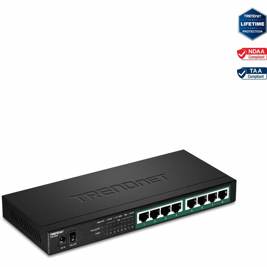
TRENDnet 8-Port Gigabit PoE+ Switch, 120W PoE Power Budget, 16Gbps…
TPE-TG84
A fanless eight-port gigabit PoE+ switch: each port sources up to 30 W, but the shared 120 W budget decides how many run at once — eight near 15 W, or four at the 802.3at maximum.
Size from the endpoints' documented maximum draw, not from the port count.
$111.24*Back-ordered802.3bt to the endpoint
Ubiquiti
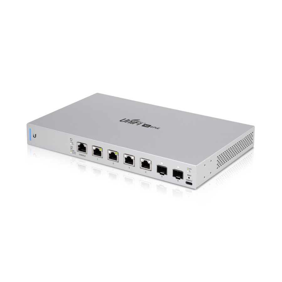
Ubiquiti 10 Gigabit 6-Port 802.3bt UniFi Switch
US-XG-6POE
A six-port 10 Gigabit switch whose four RJ45 ports source 802.3bt — the higher classes that pan-tilt-zoom cameras, multi-radio access points and powered displays ask for.
$677.59Back-ordered24 ports, 400 W budget
Ubiquiti
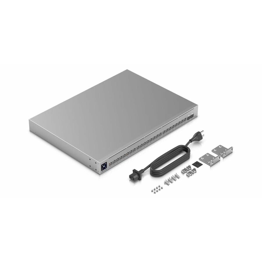
Ubiquiti Pro Max Layer 3 Switch
USW-PRO-MAX-24-POE
A 24-port multi-gigabit managed switch with a 400 W PoE budget, for a closet where the aggregate budget is what limits the deployment rather than any one port.
$1,017.93Back-orderedFrequently asked
- What is the difference between 802.3af and 802.3at?
- 802.3at is the higher-power generation, and the gap shows up at both ends of the link. 802.3af (Type 1, often labeled PoE) stops at class 3: up to 15.4 W sourced at the port and up to 12.95 W available at the powered device. 802.3at (PoE+, Type 2) adds class 4, which sources up to 30 W at the port and delivers up to 25.5 W at the device. Both run over two pairs; the later 802.3bt uses all four and adds classes 5 to 8, reaching up to 71.3 W at the device. On a bill of materials, write the IEEE standard and the class rather than the marketing name, because PoE, PoE+ and PoE++ are shorthand that does not survive a procurement dispute.
- What is the difference between 30W PoE and 25.5W at the device?
- For IEEE 802.3at Type 2, 30W is the maximum at the PSE side and 25.5W is the maximum available at the powered-device side after the standard's channel-loss allowance. Compare an endpoint requirement with the PD-side figure.
- Can every PoE-capable port deliver its maximum simultaneously?
- Only if the switch's aggregate budget and installed power supplies support the sum. Per-port capability and total budget are separate specifications. Calculate the endpoint load and compare it with the budget under both normal and redundancy conditions.
- Will a higher-power PoE port damage a lower-power device?
- Standards-based PoE uses detection and classification so a compatible endpoint receives an appropriate allocation. Do not apply that assurance to proprietary passive-power products. Verify that both source and endpoint claim the applicable IEEE standard.
- Why does an access point report reduced functionality?
- It may have negotiated a lower class than required for full radios or auxiliary features. Check the AP's power-mode documentation, switch port class, LLDP or other negotiation, cable condition, and available aggregate budget.
- Does PoE reduce the 100-meter Ethernet limit?
- No. The data-channel limit remains. Higher power increases the need to manage resistance, voltage drop, bundle heating, and ambient temperature within a compliant channel.
Sources
- 1.Ethernet Alliance — Overview of 802.3bt, Power over Ethernet Standard (per-class PSE and PD power table)ethernetalliance.org
- 2.IEEE 802.3 — PoE-plus Call For Interest (802.3af DTE power delivery: 15.4 W at the PSE, 12.95 W at the PD)ieee802.org
- 3.Ethernet Alliance — The Ethernet Alliance PoE Certification Programethernetalliance.org
- 4.Ethernet Alliance — PoE Certificationethernetalliance.org
Keep reading