
Short answer
Convert a server room's real electrical draw to heat with BTU/h = watts x 3.412, so a 5 kW rack rejects about 17,060 BTU/h. Use measured or configuration-modeled input power rather than the sum of power-supply nameplate ratings, then add in-room UPS and transformer losses, lighting, people and building gains before an engineer sizes the cooling.
Key facts
- Heat load in BTU per hour is the real IT draw in watts multiplied by 3.412, so a 5 kW rack rejects roughly 17,060 BTU/h.
- Use measured or configuration-modeled input power, not the sum of power-supply nameplate ratings — a nameplate describes capability, not consumption.
- ASHRAE's recommended range is 64.4 to 80.6 degrees F (18 to 27 C), measured at the equipment air intake rather than at a wall thermostat.
- A UPS loss belongs in the room's heat balance only when the UPS sits inside the cooled space: UPS input kW = output kW divided by efficiency.
- Lighting, people, outdoor air and the building envelope add load beyond the IT figure, and each belongs in the balance exactly once.
- Cooling tons alone do not settle it: rack inlet temperature, recirculation and air delivery decide whether the room actually works.
By Uniqcli Team
A server power consumption calculator is only as reliable as its boundary and input data. Size the room from the power equipment actually consumes, not by adding every power-supply nameplate. Build a measured or configuration-specific IT-load model, add distribution and UPS losses occurring inside the conditioned space, convert real watts to heat, then have qualified electrical and mechanical professionals apply growth, redundancy, ambient, airflow, humidity, and building-code requirements.
Define the boundary first
"Server room load" can mean several different boundaries. A rack-PDU measurement sees equipment downstream of that PDU. A UPS output includes protected loads but not the UPS conversion loss. A UPS input adds that loss. A room electrical panel may include lights or cooling equipment. A utility meter sees still more building load.
Draw the boundary before collecting numbers. Mark where utility power enters, where the UPS is located, which transformers and PDUs are inside the room, whether cooling units reject heat inside or outside the boundary, and which lighting or support loads share the space. Define the cooling boundary separately from the electrical billing boundary.
Use consistent terms:
- IT load: servers, storage, network, security, console, and other computing equipment at their input.
- Power-path loss: heat from UPS conversion, transformers, distribution, and wiring within the relevant space.
- Other sensible load: lighting, people, and powered support devices inside the room.
- Building load: heat through walls, roof, doors, windows, infiltration, ventilation, and adjacent spaces.
- Cooling load: the heat the mechanical system must remove under the design condition.
This prevents two common errors: omitting UPS loss because it is not on the output meter, and adding it even though the UPS is physically in another conditioned room.
Build the equipment inventory
Use one row per exact configuration. A product-family maximum is not enough when processor count, accelerators, drives, memory, power supplies, optics, and PoE loads vary.
- Asset and role: Exact model, configuration, service, and owner
- Power path: A feed, B feed, rack PDU, receptacle, circuit, and UPS
- Measured input: Watts, VA, power factor, date, workload, and sampling interval
- Planning input: Vendor configuration-tool estimate and operating assumptions
- Maximum/design reference: Current technical guide value and its definition
- Dynamic behavior: Idle, ordinary, busy-hour, batch, startup, and recovery states
- Growth: Approved addition or scenario, not an unnamed percentage
- Heat location: Inside room, adjacent room, or rejected elsewhere
- Airflow: Front-to-rear or other supported path, intake and exhaust locations
- Dependencies: Storage, switches, firewalls, management, KVM, and console
For an existing room, use metered rack PDUs, intelligent outlets, UPS output, server management controllers, and temporary calibrated instruments as appropriate. Record the point and accuracy class. A one-time reading during a quiet hour is not a design profile; collect normal, busy, maintenance, backup, and restart periods.
For new equipment, use the vendor's configuration-aware planning tool. Dell's Enterprise Infrastructure Planning Tool, for example, says workload materially affects consumption and advises confirming estimates with actual measurements. Treat any model as planning evidence, not a guarantee.
Do not add power-supply nameplates
A server with two power supplies rated at a particular maximum does not ordinarily consume the sum of both ratings. Those ratings describe supply capability and configuration constraints, not the system's continuous real-power draw. The server's components and workload create the demand; redundant supplies share it or one carries it after a failure according to the platform design.
Use nameplate or maximum input values where electrical code, vendor instruction, startup, fault, or safety design requires them, but do not call their sum the expected heat load. Keep the columns separate so facilities can use the appropriate value for each calculation.
For dual feeds, model at least:
- Normal load sharing
- Loss of feed A with feed B carrying the supported equipment
- Loss of feed B with feed A carrying it
- Recovery or restart load after power returns
- Maintenance state with a UPS, PDU, or cooling component unavailable
Each surviving electrical path must support its assigned failure load. The room cooling system must handle the heat produced by equipment that remains operating in the chosen failure scenario.
From watts to BTU per hour
Power consumed by servers and network equipment ultimately becomes heat in the room through processors, fans, drives, power conversion, and signals that terminate within the space. For a steady planning conversion:
- Heat (BTU/h) = real power (W) × 3.412
- Heat (kBTU/h) = real power (kW) × 3.412
The second formula uses kBTU/h, meaning thousands of BTU per hour. A 1 kW load therefore produces about 3.412 kBTU/h. Cooling tons can be expressed as:
- Cooling tons = BTU/h ÷ 12,000
This conversion does not size the complete cooling system. It translates a steady real-power load into heat. Mechanical design still considers temperature and humidity targets, airflow, equipment location, redundancy, outdoor design condition, building envelope, ventilation, fan heat, controls, and de-rating.
Use real watts, not VA, for heat conversion. VA remains important for electrical and UPS capacity. When power factor is less than one, VA can exceed watts without representing the same amount of consumed real power.
Add power-path losses correctly
If a UPS is in the server room, the difference between its input and useful output becomes heat in that room, apart from any energy crossing the defined boundary. The best method is to use measured input and output at the actual load. For planning, use the selected model's efficiency curve and operating mode.
Where efficiency is expressed as a decimal:
UPS input kW = UPS output kW ÷ efficiency
UPS loss kW = UPS input kW − UPS output kW
Efficiency changes with load and mode. ENERGY STAR evaluates UPS products at multiple loading points for this reason. Do not use a peak-efficiency headline for a lightly loaded redundant system, and do not assume eco mode if the operations plan requires double conversion.
Apply the same boundary logic to transformers and PDUs. Use current manufacturer loss data or measurement. Avoid adding a generic loss percentage to every component; doing so can be simultaneously conservative in one area and inaccurate in another.
If the UPS or transformer is outside the cooled server room, its loss may belong to another mechanical zone. It still affects facility electrical capacity and cost, but not necessarily the room's BTU/h calculation.
Add non-IT heat sources
Lighting power used in the room becomes heat. People add sensible and latent load while present, and task frequency matters for a room that is normally unoccupied. Monitors, crash carts, battery chargers, security panels, and other support devices may be small individually but should be accounted for.
Building loads can dominate a poorly located closet. Sun-exposed walls or roof, windows, an exterior door, unconditioned adjacent space, air leakage, and required ventilation change the mechanical calculation. Humidity control may add or remove latent heat and can require reheat or humidification energy.
Ask the mechanical engineer to document which loads are included. Do not add the same fan, UPS, or lighting heat once in the equipment worksheet and again in a blanket room factor.
A transparent worked example
This hypothetical example shows the arithmetic only; it is not a design recommendation.
Assume the measured/configuration-specific planning worksheet produces:
- IT equipment output load: 8.2 kW
- A UPS located in the room operating at an assumed 94% efficiency at that load and mode
- Room lighting and other measured electrical support load: 0.25 kW
- People, envelope, ventilation, and mechanical-system effects to be calculated separately by the HVAC designer
UPS input and loss:
- 8.2 kW ÷ 0.94 = 8.723 kW input
- 8.723 − 8.2 = 0.523 kW UPS loss
Known sensible electrical load in the room:
- 8.2 + 0.523 + 0.25 = 8.973 kW
Converted to heat:
- 8.973 × 3.412 = 30.62 kBTU/h
That 30.62 kBTU/h is not the final unit selection. The engineer must add the remaining room and design-condition loads, decide the required redundancy and operating margin, and verify air distribution. The assumed efficiency must be replaced with the selected UPS's current curve or measurement.
The example also shows why keeping the boundary visible matters. If the UPS were in another room, the 0.523 kW loss would not be assigned to this room's cooling load.
Electrical calculations are checks, not a design shortcut
Apparent power and current help reconcile the equipment worksheet with distribution capacity. In idealized balanced planning calculations:
- Single-phase kVA = volts × amperes ÷ 1,000
- Three-phase kVA = √3 × line-to-line volts × amperes ÷ 1,000
- Real kW = kVA × power factor
These formulas do not select a breaker, conductor, receptacle, transformer, panel, or generator. Real systems require treatment of continuous loads, harmonics, inrush, imbalance, neutral current, ambient, conductor bundling, fault current, grounding, coordination, listing, and applicable code. A licensed electrical professional must complete that design.
Use the formulas to spot mismatches. If a claimed kW, kVA, current, and power factor cannot coexist, return to the source data before procurement.
Model growth as scenarios
An unspecified "30% headroom" hides what will be added. Build named scenarios:
- Current measured busy hour
- Already approved equipment and ports
- Likely refresh with denser servers
- Maximum rack population allowed by the plan
- Loss of one electrical or cooling component
- Restart after an outage
- Future high-density or accelerator workload, if approved
For each, identify timing and confidence. A five-year maximum should not automatically drive the same day-one modular build as a signed installation due next quarter. Compare the cost of spare installed capacity with the path for adding circuits, UPS modules, racks, and cooling later.
Growth can reduce load as well as increase it. Consolidation and newer hardware may change per-workload power, while denser configurations raise per-rack demand. Keep the service forecast separate from a unit-count forecast.
Cooling capacity is not airflow delivery
A room can have enough nominal cooling tons and still overheat a server intake. Recirculated hot exhaust, blocked perforations, open rack gaps, reversed equipment airflow, poor return path, and a cooling unit located far from the dense rack can create hot spots.
Map equipment airflow. Most servers use a designed front-to-rear path, but network and storage equipment can differ. Align rack placement, doors, blanking panels, cable openings, supply, and return. Do not turn the thermostat down to compensate for recirculation without diagnosing the airflow.
Monitor temperature and humidity at equipment intake, not only at the wall thermostat or cooling return. The Department of Energy assessment guidance recommends measuring rack inlet and exhaust conditions and making the data available for analysis. In a small room, use enough points to reveal vertical and rack-to-rack variation.
The equipment vendor's permitted environmental range is not necessarily the facility's operating target, and it can change with configuration or failure mode. Have facilities set the target and alarms using current equipment and ASHRAE guidance.
Plan redundancy with usable capacity
Installed cooling capacity is not the same as usable resilient capacity. If three units are installed and one is required as standby, the room must meet its design load with the remaining units under the defined condition. The same logic applies to UPS modules, power paths, pumps, and fans.
Write the failure case. Does the standby cooling unit start automatically? Does it share air distribution? Is it on the same electrical source as the failed equipment? Can maintenance occur without losing the temperature target? How long can the room tolerate a cooling interruption given its thermal behavior?
Avoid simply labeling a design N+1. Name what "N" is, which components are independent, and what load is supported after one failure. Then test the transition and alarms.
Monitoring and acceptance
Install metering at useful boundaries: facility or room input, UPS input/output, PDU, rack, and selected outlets as scale permits. Time-align power, temperature, humidity, cooling state, and workload data. Preserve measurement units and sampling interval.
Before adding equipment, establish a baseline. After installation, run a representative sustained workload and, where approved, test redundancy. Confirm no path exceeds its design condition, rack inlets remain within the approved target, alarms arrive, and cooling responds without unstable cycling.
Reconcile three views:
- Planning tool or worksheet
- Measured electrical load
- Measured thermal and airflow behavior
Investigate the difference instead of forcing measurements to match the estimate. A divergence can reveal an incorrect configuration, unused nameplate allowance, UPS efficiency assumption, unexpected PoE load, or missing support equipment.
Show uncertainty in the worksheet
Give every planning input a source date and confidence: measured, vendor-modeled, technical-guide maximum, or assumption. Build low, expected, and high scenarios where workload or delivery timing is uncertain. Do not average unrelated peaks if they can occur together, and do not sum them blindly if an operational control prevents simultaneous operation.
For each assumption, name the decision trigger. A new storage shelf, accelerator server, higher PoE mode, or changed UPS operating mode should initiate a recalculation before installation. Compare the updated model with metered capacity and cooling observations. This makes headroom auditable and keeps an old spreadsheet from becoming an undocumented facility limit.
Buyer handoff checklist
- Define the electrical, thermal, and monitoring boundaries.
- Inventory exact configurations, dependencies, and airflow directions.
- Measure current load over representative work cycles.
- Use vendor configuration tools for uninstalled equipment and label assumptions.
- Keep nameplate, modeled, measured, and design values separate.
- Calculate watts and VA independently and model A/B failure states.
- Add in-room UPS, transformer, PDU, lighting, and support losses once.
- Convert real watts to BTU/h and identify excluded building loads.
- Model named growth, restart, maintenance, and failure scenarios.
- Have qualified professionals design circuits and mechanical capacity.
- Validate rack-level air delivery, intake conditions, and alarms.
- Store the as-built one-line, load table, heat calculation, and test results.
Common mistakes
Adding every PSU rating. It overstates expected IT heat while failing to model the actual redundant-path condition.
Using VA as watts. VA sizes electrical and UPS capacity; real watts drive the direct heat conversion.
Forgetting the boundary. A UPS loss belongs to the room only if the loss is released there.
Turning kW into a final HVAC selection. The conversion omits building, humidity, air-delivery, redundancy, and design-condition work.
Using one average reading. Busy workloads, backup, restart, and PoE changes can create different peaks.
Adding anonymous headroom. Name the equipment, date, scenario, and confidence behind growth.
Key takeaways
- Keep four values separate: equipment nameplate, modeled planning load, measured operating load, and electrical-system design load.
- Nearly all electrical power consumed by IT equipment in the room becomes heat there. For planning conversion, 1 watt equals about 3.412 BTU per hour.
- Do not add redundant server power-supply ratings as if both always consume their nameplate maximum. Model equipment input and the failure state each feed must carry.
- UPS, transformer, PDU, lighting, people, envelope, outdoor air, and other room loads belong in the heat balance when they occur in or affect the conditioned space.
- Cooling capacity is not only a total BTU/h number. Air delivery, rack inlet temperature, recirculation, hot spots, humidity, and redundancy determine whether the room works.
- Treat this method as a planning worksheet, not branch-circuit, breaker, conductor, or HVAC design.
Parts for this job
Measure before you model
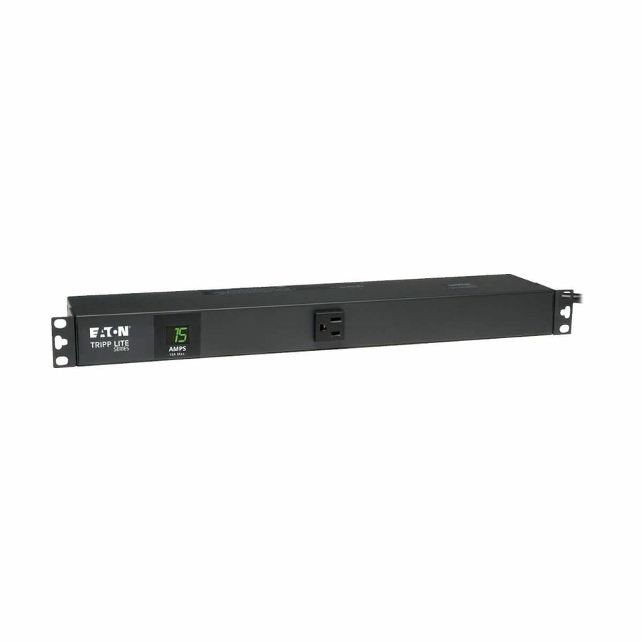
Eaton
Tripp Lite by Eaton PDU 1.4kW Single-Phase Local Metered PDU 120V…
PDUMH15
A 1U single-phase metered rack PDU with a local current display, so the heat calculation starts from what the rack actually draws rather than from a nameplate total.
$203.32Back-orderedVertical, 16 outlets
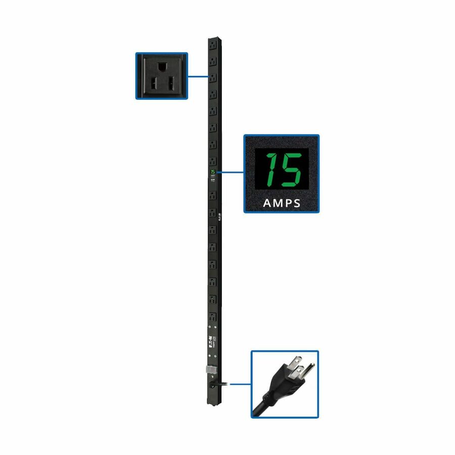
Eaton
Tripp Lite by Eaton PDU 1.4kW Single-Phase Local Metered PDU 120V…
PDUMV15
The 0U form of the same idea: a 48-inch vertical metered PDU that reads load at the cabinet without consuming a rack unit.
$259.91In stockClose the open U
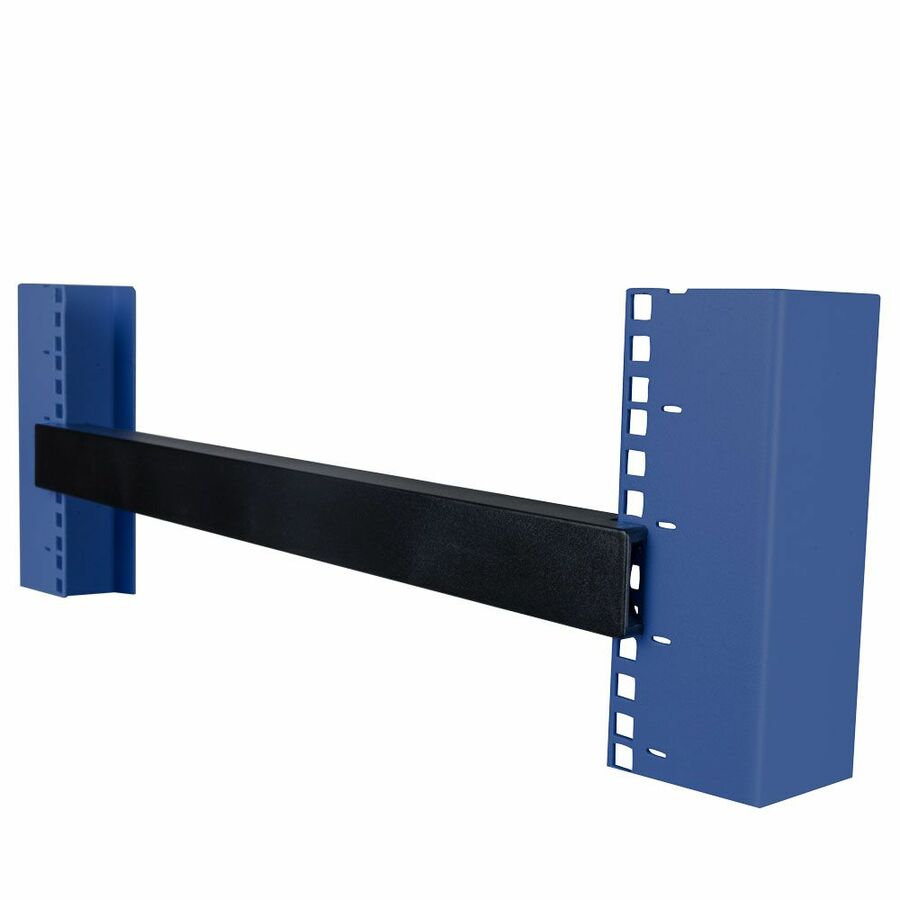
Rack Solutions
Rack Solutions 1RU Snap-In Tool-Less Blanking Panel (Plastic)
180-5745
A tool-less 1U snap-in blanking panel. Open rack units let hot exhaust loop back to the equipment intake, which is the usual reason a rack runs hot in a room with capacity to spare.
$6.32*Back-orderedFrequently asked
- How to calculate server room heat load?
- Add up the room's real electrical draw and multiply by 3.412 to get BTU per hour. Work in this order: define the boundary, total the measured or configuration-modeled IT input power, add the losses of any UPS, transformer and PDU that sit inside the conditioned space, add lighting and other support equipment, then hand the figure to a mechanical engineer to add people, outdoor air, envelope and humidity loads and to apply the design condition and redundancy. Count each source once — the most common error is adding a UPS loss in the equipment worksheet and again in a blanket room factor.
- How to calculate BTU by room size?
- You cannot size a server room by floor area. Residential and office rules of thumb that multiply square footage by a BTU figure assume the heat comes from the building, whereas in a server room almost all of it comes from the equipment, so two rooms of identical size can differ tenfold. Size from the equipment load in watts multiplied by 3.412, then treat the room's own gains — envelope, windows, an exterior door, ventilation air, lighting and occupancy — as additions the mechanical engineer calculates from the actual construction.
- Does a server use a lot of electricity?
- It depends entirely on the configuration, and the number on the power supply is not the answer. Draw scales with processor count and utilization, drive count, memory population and any accelerator, and a redundant pair of supplies does not mean the machine consumes both ratings. Take the figure from a rack PDU reading over a representative work cycle, or from the manufacturer's own configuration-based power calculator for hardware you have not installed yet; then remember that whatever the machine consumes in the room, it rejects as heat in the room.
- How many BTU per hour does a server produce?
- Use its measured or configuration-specific real power. Multiply watts by about 3.412 to estimate BTU/h released as heat in the room. A server using 500 W would represent about 1,706 BTU/h, but its power changes with configuration and workload.
- Should I use server power-supply wattage for room sizing?
- Do not use the sum as expected consumption. Power-supply ratings describe capability. Keep them for required electrical and fault checks, but use measured input or a current vendor configuration model for operating heat, then test failure states.
- Is one kilowatt equal to 3,412 BTU per hour?
- Approximately. One watt is about 3.412 BTU/h, so 1 kW is about 3.412 kBTU/h. This converts real power to heat; it does not complete the HVAC design.
- How much cooling headroom should a server room have?
- There is no universal percentage. Model approved growth, maintenance, outdoor design conditions, measurement uncertainty, and the required component-failure state. Have the mechanical engineer translate those scenarios into usable capacity and controls.
- Why is a rack hot when the room has enough cooling tons?
- The cooling may not reach the equipment intake. Recirculation, blocked paths, mixed airflow, cable obstruction, open rack spaces, or poor supply/return placement can create a local hot spot despite sufficient nominal capacity.
Sources
Keep reading