
Short answer
Rack depth is the front-to-rear dimension of the cabinet, and it is set by the installed envelope — chassis, rails, rear connectors, cable bend, PDUs and door clearance — not by the 19-inch mounting width. Common server enclosures land between about 1070 mm and 1200 mm deep; a cabinet holding only patch panels and switches can be far shallower. Size it from the deepest device's own rail matrix.
Key facts
- The 19-inch figure is a mounting width, not a depth. Two 19-inch cabinets can differ by 100 mm or more front to back.
- APC's NetShelter SX AR3100 is 42U at 1991 mm high, 600 mm wide and 1070 mm deep.
- APC's NetShelter SV AR2500 is 42U at 600 mm wide and 1200 mm deep — same height class and width, 130 mm more room behind the rails.
- Chassis depth is not rail depth. Rails describe supported post spacing, the chassis is the equipment body, and neither includes connectors or cable bend.
- Depth follows the deepest device in the cabinet, not the device count, which is why a network rack and a server rack of the same height differ.
By Uniqcli Team
The right rack depth for servers comes from the complete installed envelope, not the chassis alone. Verify the exact rail adjustment range and rack-hole type, then account for bezel, handles, rear connectors, cable bend radius, strain relief or cable-management arm, vertical PDUs, doors, airflow, slide-out service, weight, casters, anchoring, and the room’s delivery and aisle clearances.
"Rack depth" can mean five things
Procurement requests often say "42U deep rack" or "standard server rack." The first mixes height with depth; the second assumes a standard covers more than it does. Use explicit fields.
Cabinet external depth
This is the overall front-to-back footprint, potentially including doors, hinges, handles, panels, and frame. It determines room fit and delivery constraints. It does not state how much mounting or cable space is available inside.
Usable internal depth
The interior envelope available for equipment, rails, connectors, power distribution, and cables. Doors, frame members, roof openings, braces, fans, locks, and accessory channels can reduce usable space in particular locations.
Front-to-rear mounting-post spacing
The distance between the front and rear vertical mounting flanges. Adjustable posts let one enclosure serve different rail kits, but moving a post changes the front and rear cable volumes. The required spacing must fall inside the rail’s supported adjustment range for the rack’s flange type.
Chassis depth
The equipment manufacturer's chassis dimension. Determine exactly what its endpoints include. A specification may exclude bezel, handles, power cords, transceivers, or cable-management accessories.
Service depth
The room needed to install, remove, or fully extend equipment on sliding rails. It includes open doors and the technician’s safe work area. Service depth belongs to the room layout even though it is not part of the cabinet product dimension.
A rack can pass one measure and fail another. Record all five.
What the 19-inch standard covers
IEC 60297-3-100 defines basic dimensions for the 482.6 mm, or 19-inch, series of panels, subracks, chassis, racks, and cabinets. The familiar 19-inch designation describes the equipment-mounting series; it does not establish one universal cabinet depth.
Rack height is measured in rack units, where one U is 44.45 mm or 1.75 inches. Height and depth are independent. A 42U cabinet can be shallow or deep, and two cabinets with the same U count may have very different post spacing and cable capacity.
The mounting interface can use square holes, unthreaded round holes, or threaded round holes, and rail support varies. Some tool-less rails support only selected flange types; another kit may require tools or adapter hardware. A rail marketed for a 19-inch rack is not evidence that it fits every 19-inch rack.
Use the exact server vendor’s rail compatibility matrix. Dell's server manuals, for example, direct buyers to rail data that includes adjustability ranges, rack-flange types, and depth with and without cable-management accessories. That is the level of evidence the BOM needs.
Start with the deepest approved equipment
Create an equipment-depth register before selecting the cabinet.
- Exact equipment: Manufacturer, model, configuration, orientation
- Chassis depth: Current technical drawing and what the dimension includes
- Rail kit: Exact part, fixed/sliding, adjustment range, flange/hole support
- Front projection: Bezel, handles, display, air intake, pull clearance
- Rear projection: Power supplies, connectors, optics, handles, exhaust
- Cable envelope: Connector body, bend radius, strain relief, service loop
- CMA/SRB: Cable-management arm or strain-relief bar depth and movement
- Service method: Full extension, lift, rear replacement, tool clearance
- Weight: Installed, service, and shipping values as applicable
- Airflow: Intake, exhaust, and supported orientation
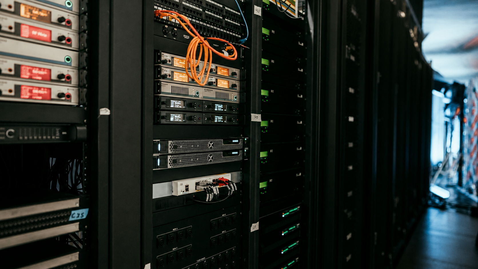
Include servers, storage, UPS units, KVMs, console drawers, switches, patch panels, and appliances. The deepest server is not always the governing item. A rear-cabled storage shelf or UPS battery module may require more connector or lifting clearance.
If the future equipment is unknown, define the design envelope the rack will support rather than claiming universal compatibility. A deeper cabinet can preserve options but also consumes floor space, increases delivery difficulty, and can make short network equipment harder to cable unless managed deliberately.
Chassis depth is only the starting number
A bare chassis dimension omits several volumes.
Front clearance. A bezel, filter, handles, status panel, drive service, or cold-air intake needs space behind the front door. The server must not press against the door or obstruct intake.
Rear connector envelope. Power cords, network plugs, DACs, optical transceivers, serial or video connectors, and retention clips project behind the chassis. Right-angle cords can change the envelope but are usable only if they meet the equipment and electrical requirements.
Cable bend radius. Copper and fiber assemblies need their manufacturer-specified minimum bend and strain limits. A closed door must not crush a bundle or lever a transceiver in its cage.
Service loop and movement. Sliding equipment requires enough cable movement to extend without unplugging where that is the supported service design. A fixed server may still need slack for safe removal.
Air exhaust. Cable bundles, PDUs, and a shallow rear door cannot block fans or trap hot air. Depth planning and airflow planning are the same decision at the rear of a dense rack.
Rails decide fit
The rail kit has an adjustment range measured between mounting flanges. It also has supported rack types and a mechanical interface to the chassis. Record the exact part rather than "rails included."
Check:
- Two-post versus four-post support
- Square, unthreaded round, or threaded hole support
- Minimum and maximum post spacing
- Fixed, static, or sliding behavior
- Full extension and service position
- Tool-less versus tooled installation
- Server or chassis weight limit
- Depth with CMA, strain-relief bar, or brackets
- Interference with rack sides, PDUs, doors, and adjacent equipment
- Whether adapters change the range or support terms
Do not alter or drill a rack, rail, or chassis unless the manufacturers explicitly support the method. A fabricated fit can defeat load rating, retention, grounding, seismic qualification, warranty, or safe service.
For a mixed fleet, create a rail-to-rack matrix. One cabinet post position may not suit every rail kit. Adjustable posts can sometimes be staggered by rack zone only if the enclosure supports it; otherwise select compatible rails or separate equipment classes.
Cable-management arms change the rear envelope
A cable-management arm, or CMA, retains and folds cables as a sliding server moves. It can make front service practical, but consumes rear depth and width and can interact with vertical PDUs.
Dell's current XR7620 installation documentation illustrates the issue: it discusses rail depth with cable-management accessories and notes potential interference between CMA hardware, rear PDUs, and the door. The lesson is not that one Dell rail defines every rack; it is that CMA depth must appear as a separate BOM field.
Build and test the cable pack. Count every power cord, data cable, fiber, management cable, and accessory. Confirm allowed bend radii through full travel. Avoid binding, pinching, or pulling connectors. Make sure the arm locks and releases without contacting equipment above or below.
If the design omits a CMA, use the vendor-supported strain relief and service procedure. Technicians need to know which cables must be disconnected before extension and how they are labeled for reconnection.
Vertical PDU placement can steal depth
Zero-U vertical PDUs save rack units but occupy rear side space. Their chassis, breakers, outlets, plugs, power cords, network modules, and mounting brackets can overlap the server, rail, CMA, or rear-door volume.
Draw the rear elevation and plan view. Show PDU side, outlet orientation, plug dimensions, redundant A/B cord paths, network modules, upstream power entry, cable managers, hinges, and door swing. Confirm that a failed PDU can be replaced without removing unrelated production equipment if that is an operational requirement.
Do not place both redundant server cords where one accidental movement or failed PDU removes both paths. Separate and label A and B distribution according to the power design. Depth must allow that separation without crossing hot exhaust or exceeding cord bend and retention limits.
Some wider cabinets provide side channels that reduce PDU conflict. Width can therefore solve a depth and cabling problem, but it changes floor footprint and aisle planning. Compare the whole enclosure, not depth alone.
A practical depth worksheet
Use the front mounting plane as a reference and build an envelope from verified dimensions.
- Required rear envelope = chassis projection behind front plane + rear connector/cable envelope
Then compare it with the cabinet drawing at the planned post position:
- Available rear envelope = rear-door inner plane − front mounting plane − fixed obstructions
Pass only if available space exceeds the required envelope with the approved service and airflow allowance. Do the equivalent front-side check for bezel and intake clearance.
A hypothetical arithmetic example:
- Chassis projection behind the front plane: 790 mm
- Verified connector, bend, and service envelope: 120 mm
- Required rear envelope: 910 mm
That does not mean any cabinet advertised as 910 mm deep will fit. External depth includes frame and doors, and the post position plus internal obstructions determine available space. Use the candidate cabinet’s internal drawing, then physically test the exact BOM.
For a CMA, use the rail vendor's maximum installed depth through its full movement rather than adding a guessed cable allowance. The largest result among equipment items becomes the rack's equipment-depth requirement; service aisle is calculated separately.
Airflow and doors
Most rack servers are designed for front-to-rear airflow, but verify every device. A switch with side-to-side airflow can recirculate hot air in a server enclosure unless ducting, placement, or a compatible model addresses it.
The front door and any filter must provide the equipment's required intake path. The rear door and cable field must release exhaust. Perforation percentage alone does not prove adequate cooling because pressure, blanking, containment, fan behavior, and obstructions matter.
Use blanking panels in unused rack spaces where the thermal design calls for them, and seal inappropriate cable openings to reduce recirculation. Keep cable bundles out of exhaust. Measure intake temperatures at useful vertical positions after installation and under representative load.
A deeper cabinet can improve rear cable volume, but it cannot fix a room with poor supply and return air. Tie the rack design to the server-room cooling and aisle plan.
Service clearance belongs outside the rack
Sliding rails allow a server to extend for service. The front aisle must accept the extended chassis, open door, rail motion, lift or technician, and safe egress. Rear service requires the rear door to open and a technician to reach power supplies, cables, fans, and PDU components.
Measure the room with doors, columns, cooling units, panels, fire equipment, ramps, and neighboring racks shown. Respect working clearances around electrical equipment and required paths of egress; qualified facilities personnel must apply the governing code.
Door removal or reversal may improve service but changes the written procedure. Schneider Electric's current NetShelter manuals cover door removal/reversal, adjustable flanges, leveling, joining, grounding, and securing. Follow the exact enclosure manual rather than treating these as generic permissions.
Weight, stability, floor, and movement
Depth and weight interact. A long server extended on rails moves the center of gravity forward. Enclosure manuals warn about tip hazards and define leveling, stabilizing, joining, and anchoring requirements. Install heavy equipment in the supported sequence and location.
Keep these ratings separate:
- Static rack capacity in its installed state
- Dynamic or rolling capacity while moving
- Shipping capacity if equipment remains installed in transit
- Rail and shelf load rating
- Raised-floor or structural capacity
- Point loading at casters or leveling feet
Do not assume the static cabinet rating applies while rolling. Have facilities verify slab or raised-floor loading, seismic or anchoring requirements, and the path from loading dock to final position.
The delivery route can reject an otherwise suitable rack. Measure doorways, elevators, corners, slopes, thresholds, ceiling height, dock, and floor protection. Include packaging dimensions if the cabinet arrives assembled and determine whether doors or panels may be removed under the manual.
Doors, casters, and external depth
External-depth specifications may be affected by door shape, split rear doors, handles, hinges, bumpers, and casters. A rear split door can reduce swing radius without increasing internal equipment space. Casters raise the rack and may change total height, stability, and leveling procedure.
Confirm whether doors can close with all cables installed and whether locks clear connectors. If a project plans to operate without doors, facilities and security must review airflow, containment, access, noise, and physical protection.
Account for wall and aisle clearance behind the external door, not just the cabinet body. A rack that fits between walls while closed may be impossible to cable or service.
Growth and mixed-depth equipment
Select growth deliberately. List the known refresh candidates and their rail envelopes. If future server dimensions are uncertain, state a maximum supported envelope and reserve rack, power, cooling, and floor capacity for it.
Mixing deep servers and shallow switches can create cable-management challenges. Avoid mounting a shallow rear-cabled device where its connections collide with a deep server CMA. Use supported shelves or alternate post locations where the rack and device permit them. Keep patching and power serviceable without reaching through hot exhaust.
More depth is not free. It consumes room area, can reduce aisle clearance, increases cabinet mass and delivery difficulty, and may encourage unmanaged cable storage. Buy enough verified internal envelope and service margin, not the largest cabinet by reflex.
Rack BOM and fit-test checklist
- Exact cabinet, doors, side panels, roof, base, casters, and anchoring kit.
- Exact server/appliance configuration and weight.
- Exact rail, adapter, shelf, CMA, and strain-relief parts.
- Front-to-rear post spacing and flange/hole type.
- Front bezel/intake and rear connector/bend envelopes.
- A/B vertical PDUs, plugs, breakers, network modules, and mounts.
- Copper/fiber bend radii, service loops, labels, and cable count.
- Airflow direction, blanking, containment, and temperature sensors.
- Static, dynamic, rail, shelf, floor, and point-load checks.
- Front/rear service aisles and electrical working clearances.
- Delivery route, packaging, elevator, doorway, slope, and floor protection.
- Grounding/bonding, leveling, joining, stabilizing, and anti-tip procedure.
Assemble one representative rack before volume shipment. Install the deepest and heaviest equipment, both PDUs, full cable pack, CMA, doors, and sensors. Extend and remove the server using the approved method. Close and lock doors, check cable strain, inspect airflow, and verify no component blocks another's service.
Acceptance and handoff
Record final post positions, equipment U locations, rail parts, torque or fastening requirements where specified, PDU positions, cord routes, grounding, anchoring, and sensor locations. Photograph the completed front and rear only under the organization's security policy.
Test door removal and opening, server extension, power-supply replacement, cable identification, PDU access, and the heaviest expected service action. Confirm that two technicians or a lift are available where the equipment procedure requires them.
Store the as-built elevation and plan view with the asset record. A future buyer should be able to decide whether a chassis fits without remeasuring a live rack or guessing from external depth.
Common mistakes
Using cabinet external depth as usable depth. Frame and doors consume space.
Checking chassis but not rails. Post-spacing range and flange type decide mechanical fit.
Forgetting the connector bend. A closing rear door can damage cables or transceivers.
Adding a CMA after the rack is full. It can collide with PDUs, door, and adjacent gear.
Ignoring full-extension service. A mounted server may be impossible to repair safely.
Treating 42U as a depth. U measures vertical mounting height.
Key takeaways
- Rack external depth, usable internal depth, front-to-rear post spacing, server chassis depth, and rail depth are different measurements.
- The rail kit — not the "19-inch" label — determines whether a particular server mounts in a particular four-post rack.
- Rear cables and a cable-management arm can require more depth than the bare chassis and can interfere with vertical PDUs or the rear door.
- Depth must preserve supported airflow and service access; a server that physically closes inside the cabinet can still be unserviceable or thermally wrong.
- Validate static and rolling load, center of gravity, leveling, anchoring, floor capacity, delivery route, and anti-tip procedure with facilities.
- Approve an exact server, rail, rack, PDU, cable, door, and accessory combination using vendor drawings and a physical fit test.
Shop it at Uniqcli
Parts for this job
Shallow depth
Eaton
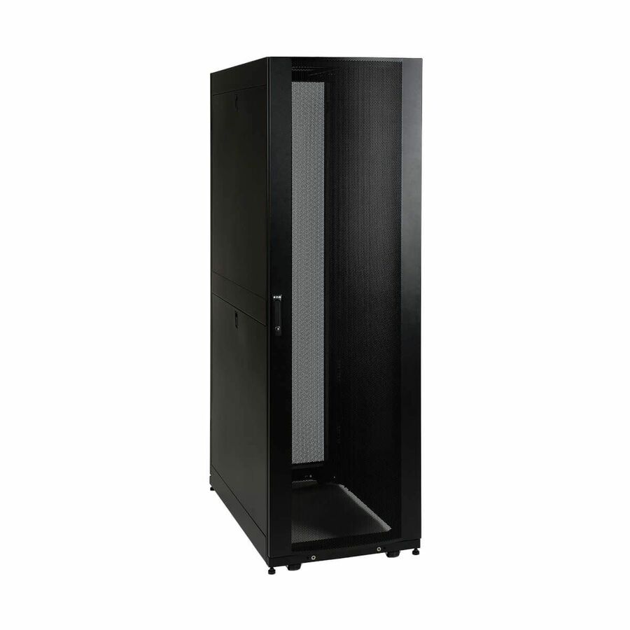
Tripp Lite by Eaton 42U SmartRack Shallow-Depth Rack Enclosure Cabinet…
SR42UBSD
A 42U shallow-depth enclosure with doors and side panels, rated 3000 lb static. For network gear and short-chassis appliances in a room that cannot give up floor space.
$2,355.38Back-ordered1100 mm
Vertiv
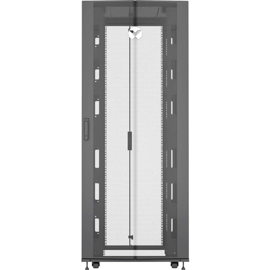
Vertiv VR Rack
VR3100-031
A 42U server enclosure with a 600 by 1100 mm footprint; the listing gives 43.90 in of rack depth. The middle size, where standard servers fit with room behind them for cabling and PDUs.
$2,428.28Back-ordered1200 mm
Schneider Electric
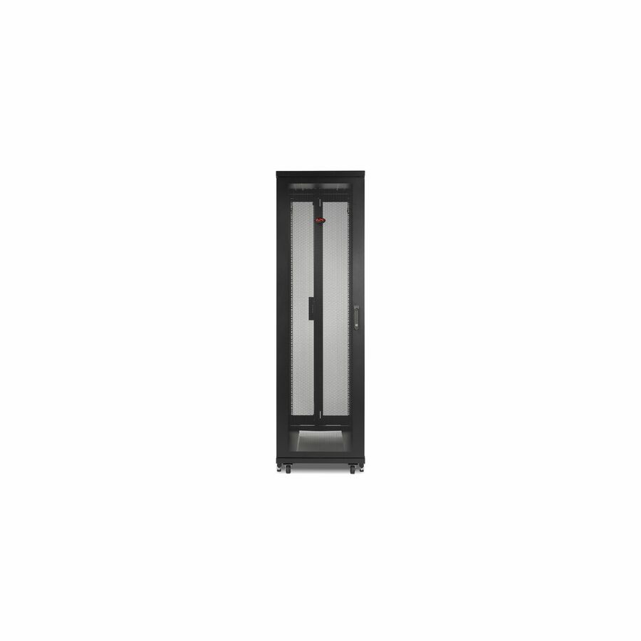
APC NetShelter SV, Server Rack Enclosure, 42U, 600W x 1200D mm…
AR2500
A 42U enclosure at 600 by 1200 mm with sides. The extra depth is for deep chassis, cable managers and rear-mounted PDUs in the same footprint width.
Measure the doorway and the aisle before choosing 1200 mm — depth is bought once and lived with.
$2,216.10Back-orderedFrequently asked
- Why are server racks 19 inches?
- Because 19 inches is the long-standing mounting width for equipment panels, and gear is built to it. What is fixed by that convention is the panel width and the hole spacing on the mounting rails — not the cabinet's depth, which is why two 19-inch racks can differ by 100 mm or more front to back.
- What is the depth of a standard rack?
- There is no single standard depth. Server enclosures commonly run about 1070 mm to 1200 mm — APC's NetShelter SX AR3100 is 1070 mm deep and the NetShelter SV AR2500 is 1200 mm — while network cabinets holding patch panels and switches are much shallower. Depth is chosen from the installed equipment, not from a default.
- What is the standard depth of a 4 post rack?
- Again, there is no one figure; four-post refers to the mounting arrangement, not a depth. What matters is the supported front-to-rear post spacing, which the rail kit publishes, and whether that spacing plus rear connectors, cable bend and door clearance fits inside the cabinet you are buying.
- What are the standard dimensions of a server rack?
- Height is counted in rack units — 42U is the common full-height size — and the mounting width is 19 inches. External width and depth are model figures: APC's NetShelter SX AR3100 is 42U at 1991 mm high, 600 mm wide and 1070 mm deep, while the NetShelter SV AR2500 is the same 42U and 600 mm wide at 1200 mm deep. Read the exact model, not the category.
- What rack depth do I need for a server?
- Use the exact server rail matrix and calculate the installed envelope for chassis, bezel, rear connectors, cable bend, CMA, PDU, doors, and airflow. There is no universal server-rack depth that fits every model.
- Is a 19-inch rack always compatible with a 19-inch server?
- No. The mounting series does not establish one depth or rail interface. Verify four-post/two-post support, hole type, post spacing, rail kit, weight, and accessory clearance.
- Is chassis depth the same as rail depth?
- No. Rail adjustment describes supported front-to-rear post spacing, while chassis depth describes the equipment body. Rails, CMA, connectors, bezel, and service movement can extend beyond it.
- How much room should cables have behind a server?
- Use the exact connector bodies, manufacturer minimum bend radii, strain relief, service loop, CMA path, and rear-door drawing. Do not apply a universal allowance across copper, fiber, power, and different chassis.
- Should I buy the deepest rack available for future growth?
- Not automatically. Extra depth uses floor and aisle space and can complicate delivery and shallow-device cabling. Define the future equipment envelope and select a cabinet that supports it with service and airflow margin.
Sources
Keep reading