
High-Density GPU Rack Power and Liquid Cooling: A Facility Readiness Guide
Modern AI systems span very different facility classes. NVIDIA's DGX B200 documentation lists a maximum input power of 14.3 kW for one 10U appliance. A rack of multiple servers plus switches and storage can move far higher. NVIDIA's GB300 NVL72 reference architecture states that a complete liquid-cooled rack can reach 142 kW. “GPU rack” therefore is not a sufficient planning unit.
By Uniqcli Team · · 6 min read · Updated
Key takeaways
- Use system- and rack-level vendor data; never estimate the facility from GPU TDP alone.
- Capture typical, tested peak and maximum loads with the assumptions behind each.
- Verify upstream electrical capacity, redundancy, connectors, protection and maintenance—not only rack PDU rating.
- Direct liquid cooling requires a defined technology-water/facility-water boundary, water quality, controls and leak response.
- Design for transients, partial failures, adjacent-rack effects and maintenance modes.
- Commission with representative heat load before accepting the production workload.
On this page
Facility readiness starts with the exact configured system, realistic workload profile and deployment pattern. It ends with commissioned electrical and cooling interfaces, alarms, failure procedures and documented ownership.
Start with a load inventory
List every device in the rack: compute, switches, storage, management, CDU pumps/controllers and auxiliaries. For each, collect quantity, typical draw under the target workload, tested peak, maximum/nameplate, heat output, airflow or liquid requirement and feed arrangement.
The DGX B200 user guide lists 14.3 kW maximum input, 1,550 CFM airflow and 48,794 BTU per hour for that appliance. These are manufacturer planning values for a specific system. Apply the same discipline to every chosen OEM model.
For rack-scale GB300, use the current NVL72 reference-architecture component data. It describes a full-rack maximum of 142 kW and integrated liquid-cooling components. Do not transpose that value to an HGX B300 server rack or assume every workload constantly reaches it.
Create at least three scenarios: idle/degraded, expected sustained mission load and maximum credible load. Include workload transients and simultaneous restart. Note whether power caps are configured, how they are enforced and what performance loss occurs when a cap is reached.
Build the electrical path
Trace from utility or generator through switchgear, UPS, distribution, busway/RPP, branch circuit, rack PDU, cord and device. Record capacity, redundancy, protection, voltage, phase, connector and monitoring at every handoff. A 60 kW rack connected to two 60 kW feeds does not necessarily have 120 kW usable capacity; an A/B redundant design may require either feed to carry the full protected load.
Review upstream diversity. Two rack PDUs can land on the same panel or UPS and share a failure domain. Confirm generator/UPS behavior, maintenance bypass, battery runtime, harmonic/current characteristics and the site's policy for continuous loading of circuits.
Power-shelf architectures deserve special attention. The GB300 NVL72 documentation describes multiple power shelves. Map every shelf to feeds and protection, and understand system behavior after a feed or shelf failure.
Produce a one-line diagram and branch schedule. Label physical receptacles and cords to match. Configure metering and alerts before burn-in. Capacity that exists only in a spreadsheet is not operational capacity.
Decide whether air cooling is viable
Air cooling can remain appropriate for many H200 and B200 server configurations, but high airflow creates constraints. Check cold-aisle supply, containment, return path, static pressure, fan curves, floor/tile or duct delivery, allowable inlet temperature, altitude derating and neighboring loads.
Assess the room, row and rack. A room may have enough aggregate tons while one aisle recirculates hot exhaust. A rack may receive adequate average airflow while top servers ingest hotter air. Use temperature and pressure sensors at multiple heights and observe behavior with doors and containment in their final state.
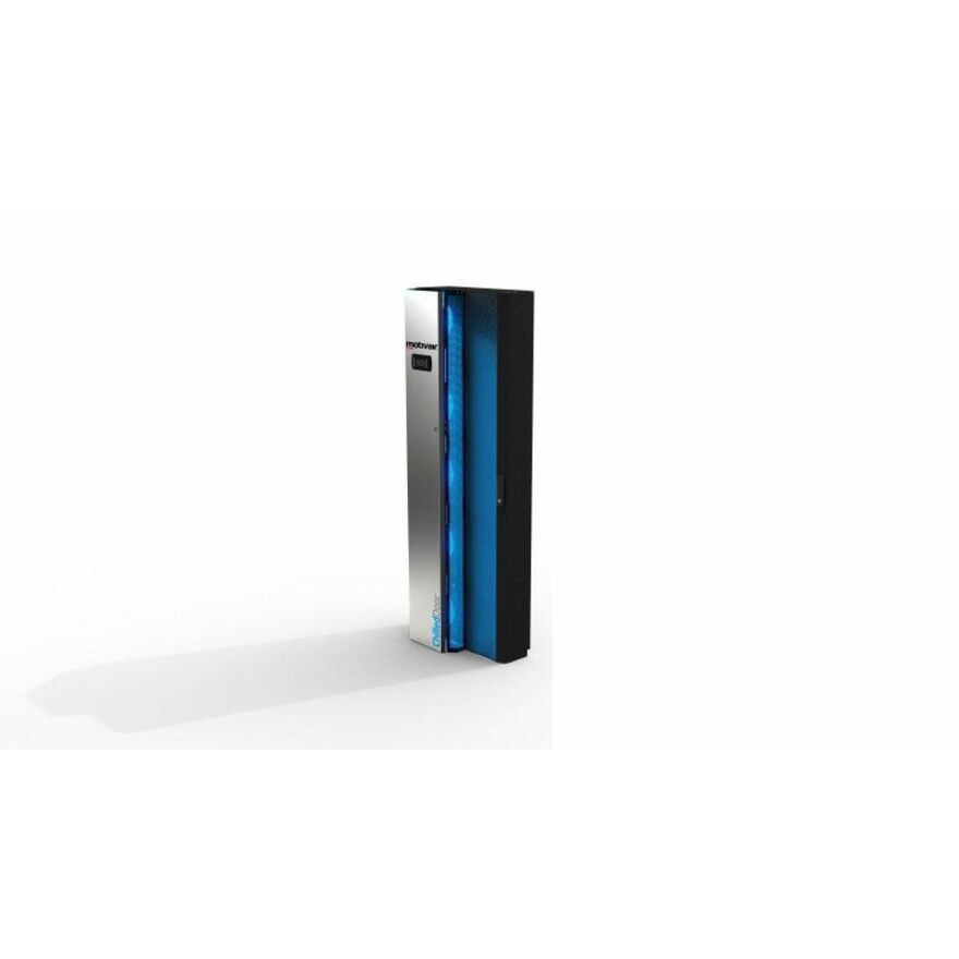
Rear-door heat exchangers can remove heat near the rack but introduce water, door weight, hose routing and maintenance concerns. They do not reduce electrical load. Specify approach temperature, flow, pressure drop, condensate policy, leak detection and behavior when the door is open or exchanger unavailable.
If the air-cooled design requires extreme fan energy, noise or room changes, compare direct liquid cooling on lifecycle and schedule—not just equipment cost.
Design the liquid-cooling boundary
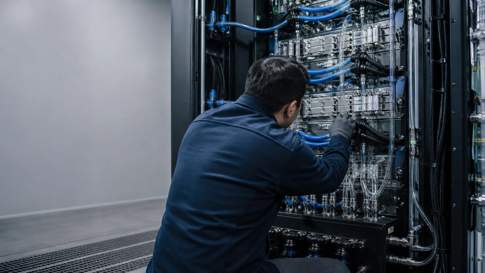
Direct liquid cooling commonly uses a technology cooling system that interfaces with a facility water system through a coolant distribution unit. Define which party owns:
- Server cold plates and internal hoses.
- Rack manifold and quick disconnects.
- Technology coolant and water-quality control.
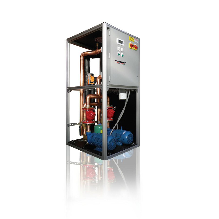
- CDU heat exchanger, pumps, filters and controls.
- Facility supply/return piping and heat rejection.
- Leak detection, containment, drains and emergency response.
Obtain required supply temperature, allowable return, flow, pressure, pressure drop, coolant chemistry, particulate limits, materials compatibility and dew-point margin. Values vary by manufacturer and configuration. Use the exact site-preparation guide and approved fluids.
Design hose routing for service. Avoid bend, strain and trip hazards. Confirm dripless connector performance, labeling and keyed/mistake-proof connections. Account for expansion, purge/fill, trapped air and maintenance access.
Condensation risk depends on fluid temperature and room dew point. A colder loop is not automatically better. Instrument and control the system to remain within vendor and environmental limits.
Plan CDU, water and controls
Size the CDU for expected and maximum heat load, flow/pressure requirements, growth and redundancy. State whether N+1 means pumps, CDUs, heat exchangers or the full cooling path. Confirm power feeds for pumps and controls; a protected compute rack with an unprotected cooling controller has an incomplete availability design.
Place the CDU based on pipe length, floor loading, service clearance, containment and leak consequences. An in-row, in-rack or facility-level CDU changes responsibility and failure domains. Coordinate with fire protection, drainage and building controls.
Water quality is a lifecycle process. Specify sampling, filtration, treatment, corrosion monitoring, microbial control where applicable and recordkeeping. Materials from server cold plates through facility piping must be compatible. Do not introduce an unapproved additive because it is convenient locally.
Integrate telemetry: supply/return temperature, flow, pressure, pump state, filter differential, leak detection, conductivity/quality indicators and rack load. Define alert thresholds, recipients, retention and automated protective actions. Avoid an automatic shutdown that creates a worse mission outcome without approved sequencing.
Design failure and maintenance modes
Analyze loss of one utility feed, rack PDU, server power supply, pump, CDU, facility-water loop, sensor, controller, network management path and leak-detection zone. For each, state remaining capacity, system response, workload action, alarm and recovery.
Determine ride-through time. Thermal mass and coolant volume may provide seconds or minutes, not a maintenance window. Coordinate power and cooling shutdown sequences so pumps do not stop before compute load falls. Test emergency power-off and leak response under controlled conditions.
Plan maintenance with the system running and stopped. Can a filter, pump or hose be serviced without draining the full loop? Is isolation available at rack and device level? Are caps, absorbent materials, spill kits, replacement hoses and approved coolant on site? Who is authorized to disconnect liquid lines?
Consider workload placement. Orchestration may drain nodes before maintenance or enforce rack power caps. Document the control integration and ensure facilities does not assume the AI platform will shed load unless that behavior has been tested.
Commission and document
Before compute installation, pressure-test and flush/purge the loop under the approved procedure. Verify water quality, sensor calibration, valve position, controls communication and leak detection. Inspect electrical torque, grounding, phase balance, cord mapping and protective settings.
Use staged load. Start pumps/controls, energize infrastructure, bring up nodes in sequence and run a representative workload long enough to reach thermal equilibrium. Capture rack power, branch currents, supply/return temperatures, flow, pressure, component temperatures, fan/pump behavior and alarms.
Test failures: remove a feed, fail a pump or simulate an allowed sensor/alarm condition under manufacturer/site direction. Verify workload response and recovery. Complete the acceptance record with readings and thresholds.
Deliver one-line electrical, mechanical flow diagram, rack elevation, equipment schedules, set points, alarm matrix, water baseline, test results, maintenance plan and ownership/escalation contacts. Update them after every material configuration change.
Can an 80 kW GPU rack be cooled with air?
Do not answer from rack watts alone. Some specialized facilities can deliver very high airflow or use rear-door heat exchange, but feasibility depends on server airflow, inlet limits, containment, static pressure, room/row heat rejection, noise, altitude, redundancy and adjacent loads. Direct liquid cooling often becomes more practical at high density, yet it adds water and controls interfaces. Ask the server manufacturer and qualified facility engineer to compare complete air, rear-door and direct-liquid designs for the actual site and workload.
How Uniqcli can support readiness
Uniqcli can connect the selected AI server rack to a configuration-specific power and cooling assumption sheet, integrated BOM, rack elevation and factory test. Request a facility-readiness review before hardware is ordered.
Final building design, stamped engineering and authority approval remain with qualified site professionals. The integration goal is to give them verified equipment data and interfaces early enough to avoid a delivery-day surprise.
Engineering note: Power and liquid-cooling values are safety- and configuration-sensitive. Use current manufacturer site-preparation documents and qualified electrical/mechanical professionals.
Coolant distribution, rear-door and in-row units this catalog carries
Motivair
Motivair High Capacity Coolant Distribution Unit
$46,798.20Back-orderedMotivair
Motivair ChilledDoor Cooling System
$28,472.76Back-orderedSchneider Electric
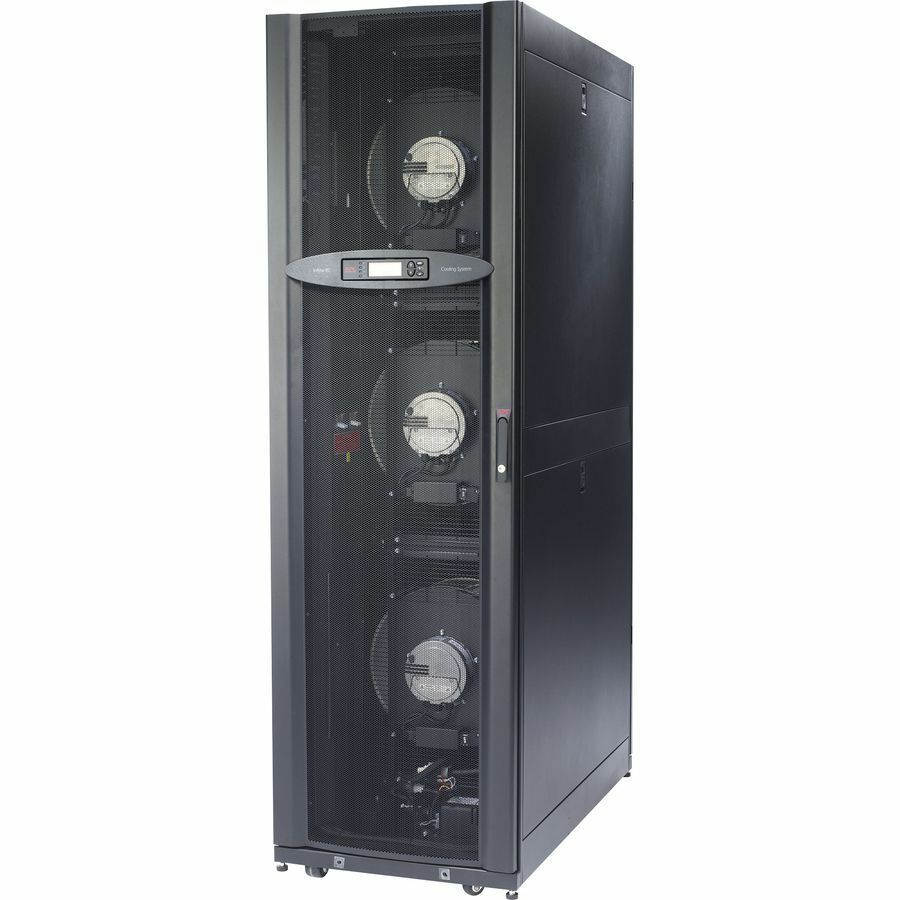
APC by Schneider Electric InRow RC Cooling System
$27,429.80Back-orderedEaton
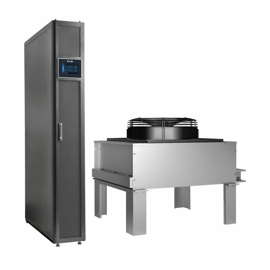
Tripp Lite by Eaton In-Row Precision Cooling System
$52,607.34Back-ordered
Keep reading